


TPS22946 Load Switch: 7 Checks for Sampled Limits and Fault Windows

TPS22946 Load Switch: 7 Checks for Sampled Limits and Fault Windows
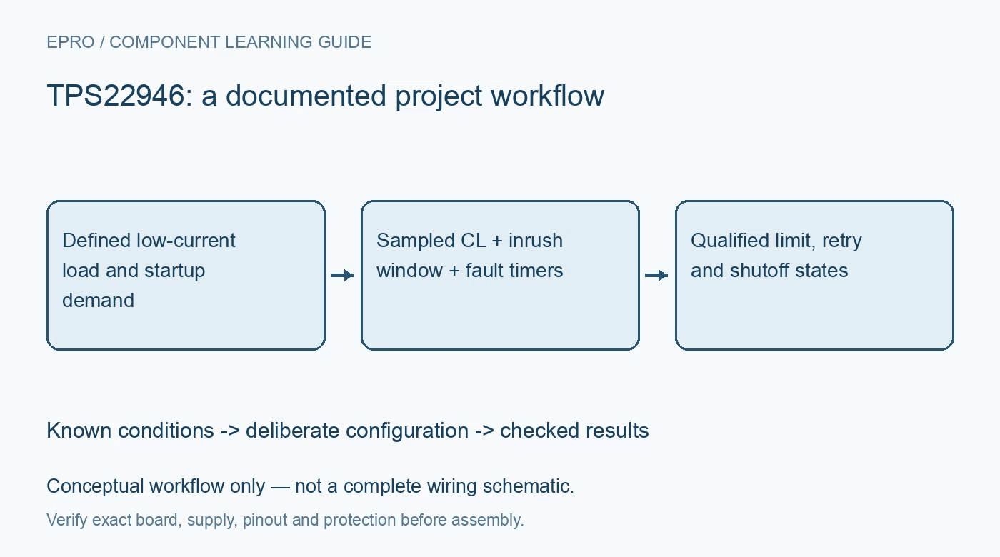
TPS22946 checks for startup-sampled CL states, limit tolerances, elevated inrush current, fault blanking, retries and shutoff. This is a documentation-based planning guide, not a report of independent hands-on testing.
1. Treat limit labels as conditions rather than calibration
The TPS22946 operates from 1.62 V to 5.5 V and provides selectable current-limit behavior. The familiar 30, 70 and 155 mA labels are not three exact calibrated trip currents. Consult the electrical-table limits at the relevant supply and output conditions. For example, at the documented 1.8 V test point, floating CL corresponds to 30 mA minimum, 45 mA typical and 60 mA maximum. Define the acceptable protected-load range using those tolerances rather than the smallest number in the feature list. Manufacturer documentation.
2. Set CL before enabling the switch
CL low selects the lower driven setting, CL high the higher setting, and a deliberately high-impedance CL state selects the third setting. The device samples this control during startup from a disabled state; changes afterward are ignored until the next startup cycle. Do not present CL as a continuously programmable current-control input. Drive levels must be referenced to VIN and meet the specified thresholds. Record the sampled state together with the enable sequence so firmware logs do not imply an unaccepted runtime change took effect. Manufacturer documentation.
3. Preserve the real floating-state requirements
The floating selection has explicit loading requirements: total CL capacitance below 100 pF and resistive loading above 10 megohms. A test probe, pull resistor, leakage path or host pin configuration can prevent that intended state. Driven selections have their own low-impedance connection guidance. Inspect the complete board and measurement fixture rather than assuming an unconnected schematic net is electrically floating. Verify the startup selection with bounded load behavior before relying on it to protect a low-current subsystem. Manufacturer documentation.
4. Budget the elevated startup current window
After an ON rising transition, the device temporarily permits a higher inrush limit for approximately 8 ms to support downstream startup. The 435 mA figure is typical under specified conditions; the electrical table includes a substantially wider range, including a 685 mA maximum at its stated test point. A load expecting an immediate thirty-milliamp ceiling can therefore be exposed to much more current during startup. Check downstream absolute ratings and stored energy separately instead of assuming the normal limit applies from the first instant. Manufacturer documentation.
Newest in the store


5. Distinguish limiting from delayed fault indication
Persistent overcurrent enters the documented blanking and retry state machine rather than producing an instantaneous permanent disconnection. The table gives a 7 to 15 ms blanking range around 10 ms typical and a 50 to 95 ms restart range around 70 ms typical. OC is an open-drain fault indication, not an analog current readout. Capture current, output voltage and OC together. A status pin that has not yet asserted cannot prove that every earlier current pulse stayed below a load’s damage threshold. Manufacturer documentation.
6. Review permanent-fault shutoff and reset carefully
The documentation describes eventual shutoff for persistent faults, with five-second descriptions and a 6000 ms timeout entry under specified conditions. Do not turn those into an exact universal five-second safety deadline. Recovery behavior also depends on fault type; review the detailed state diagrams and use a verified power-reset procedure when necessary rather than assuming endless automatic restart. Thermal behavior is another distinct path. Test only bounded fault simulations in a protected fixture, and retain independent upstream protection where the application requires it. Manufacturer documentation.
7. Qualify the complete state machine at modest energy
Record VIN, sampled CL loading, ON transitions, startup current, steady-state limit range, OC timing and retry behavior. Include the actual downstream startup load because a resistor and an LDO can demand current differently. Verify that firmware can distinguish startup allowance, limiting, retry-off intervals and permanent shutoff. The acceptance record should establish behavior within specified tolerances without treating selectable limit labels as precision thresholds or a multi-stage protection state machine as an instantaneous zero-energy disconnect. Manufacturer documentation.
Related reading: TPS22950 Load Switch: 7 Checks for Current Limits and Fault Meaning.
Catalog note: The exact-part search did not return a matching Epro listing during preparation. Check the current catalog; this guide makes no price, availability or included-accessory claim.