


TCA9800 I2C Buffer: 7 Checks for B-Side Current and Pullup Placement

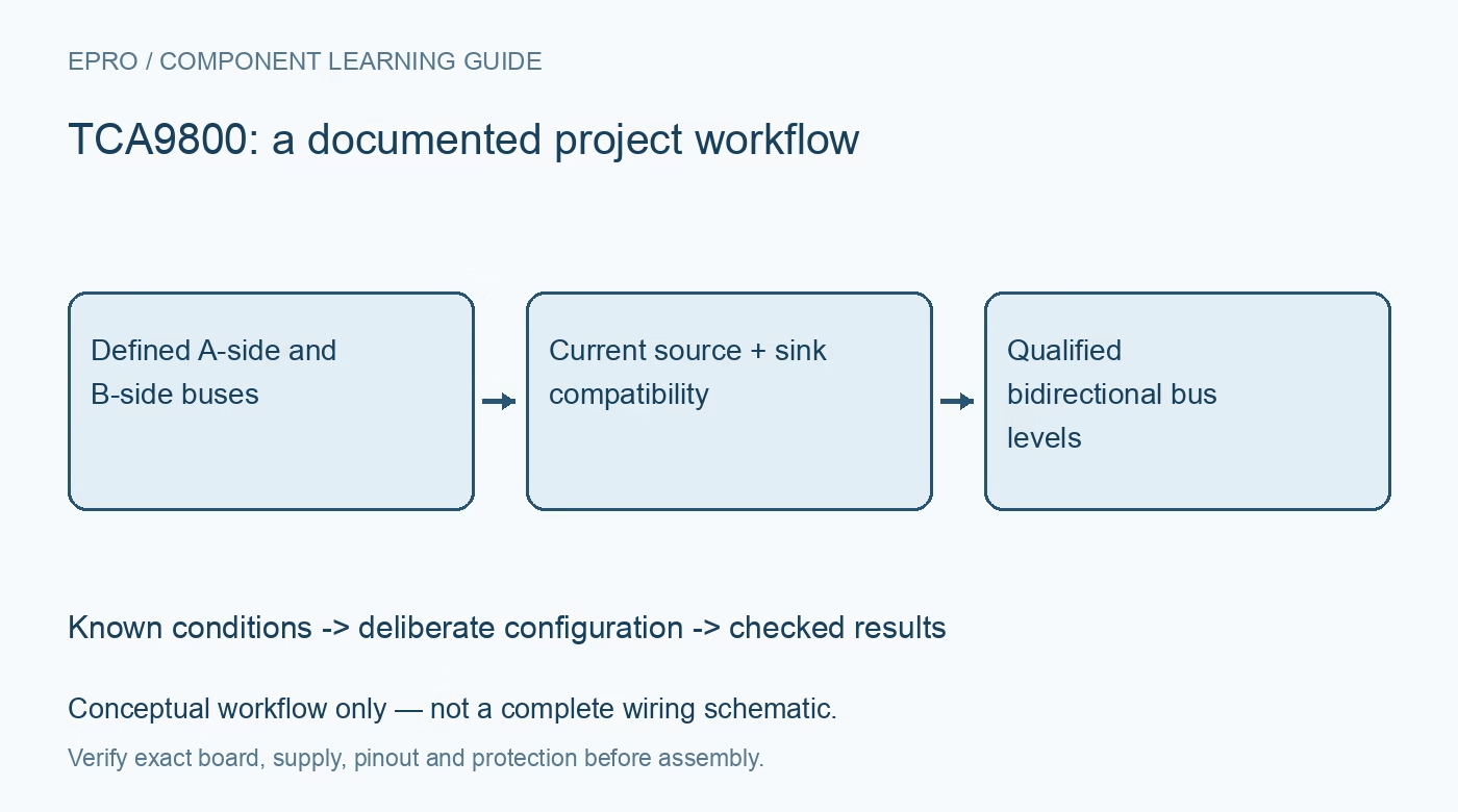
TCA9800 I2C Buffer: 7 Checks for B-Side Current and Pullup Placement
Plan TCA9800 I2C segments with B-side current-source rules, A-side pullups, sink-current compatibility and realistic power-off behavior. This is a documentation-based planning guide, not a report of independent hands-on testing.
1. Assign the A and B segments before adding resistors
The TCA9800 is a bidirectional I2C buffer with electrically different A and B sides. VCCA operates from 0.8 to 3.6 volts and VCCB from 1.65 to 3.6 volts. Within those ranges, the supplies may be equal or either may be higher; do not invent a mandatory rail order. Label the controller, targets, segment capacitance and rail attached to each port. Identify hidden pullups on every breakout board before deciding that a schematic contains no external B-side pullup. Manufacturer documentation.
2. Keep conventional pullups on the correct side
The A side uses conventional external pullups. The B side instead has internal current-source pullup circuitry, and TI explicitly says not to add external B-side pullup resistors. The TCA9800 nominal source is 0.54 milliamps, not the 3.3-milliamp value of the TCA9803. These family variants are not interchangeable timing assumptions. Removing a visible resistor is insufficient if another connected module or test instrument still sources current onto that bus. Audit the complete connected segment. Manufacturer documentation.
3. Check B-side sink recognition, not only voltage low
The B-side buffer uses current sensing to identify an external device pulling low. A target must meet the documented low-level sink-current requirement as well as producing a sufficiently low voltage. External sourcing current can increase the sink requirement and interfere with direction detection. Consult the IILC and IEXT conditions rather than choosing a resistor from a generic I2C formula. A static low measured with a multimeter does not prove correct buffer behavior during arbitration or clock stretching. Manufacturer documentation.
4. Select the family variant from capacitance and speed
Estimate bus capacitance from traces, connectors and all attached pins, then check the rise-time requirement at the intended clock rate. A smaller internal source saves current but may not charge a large B-side capacitance quickly enough. Do not describe every TCA980x variant as supporting the same maximum load at the highest bus rate. Confirm high and low timing margins with the actual population. Keep voltage-domain translation and capacitance buffering as separate requirements in the design record. Manufacturer documentation.
Newest in the store


5. Review cascades and pass-gate translators explicitly
A translator based on a passive FET often needs pullups on both sides and can couple external source current into the TCA9800 B port. TI warns that such arrangements can violate the B-side external-current conditions. Do not transplant a permitted topology from an offset-based buffer family and assume it remains valid here. Review the manufacturer connection examples for the exact neighboring devices. When uncertain, redesign the segment boundary rather than adding stronger pullups until a limited bench transaction happens to pass. Manufacturer documentation.
6. Distinguish disabled operation from all pins floating
EN low disables the outputs, while EN high permits buffering. Power-off protection addresses back-powering, but the B-side current-source table also describes a weak pullup with back-power protection when VCCB is low. It is therefore inaccurate to summarize every unpowered bus terminal as an ideal open circuit. Verify supply-off and controller-reset behavior with the intended external devices attached. Define EN electrically and examine idle bus levels before enabling communication, especially when one segment remains powered during maintenance. Manufacturer documentation.
7. Qualify bidirectional traffic and retain the topology
Start slowly with bounded low-voltage rails, then check reads, writes, repeated starts, clock stretching and recovery from a deliberately held-low line. Observe both sides simultaneously where possible and assess rise time, low voltage and direction changes. Record the exact family variant, rail values, A-side pullups, measured capacitance estimate and B-side device sink capability. Mark measured results separately from datasheet expectations. A single acknowledged address is not proof that a mixed-voltage multi-device bus is reliable across its operating conditions. Manufacturer documentation.
Related reading: TCA9803 I2C Buffer: 7 Checks Before Adding Pull-Ups.
Catalog note: The exact-part search did not return a matching Epro listing during preparation. Check the current catalog; this guide makes no price, availability or included-accessory claim.