


TCA9803 I2C Buffer: 7 Checks Before Adding Pull-Ups

TCA9803 I2C Buffer: 7 Checks Before Adding Pull-Ups
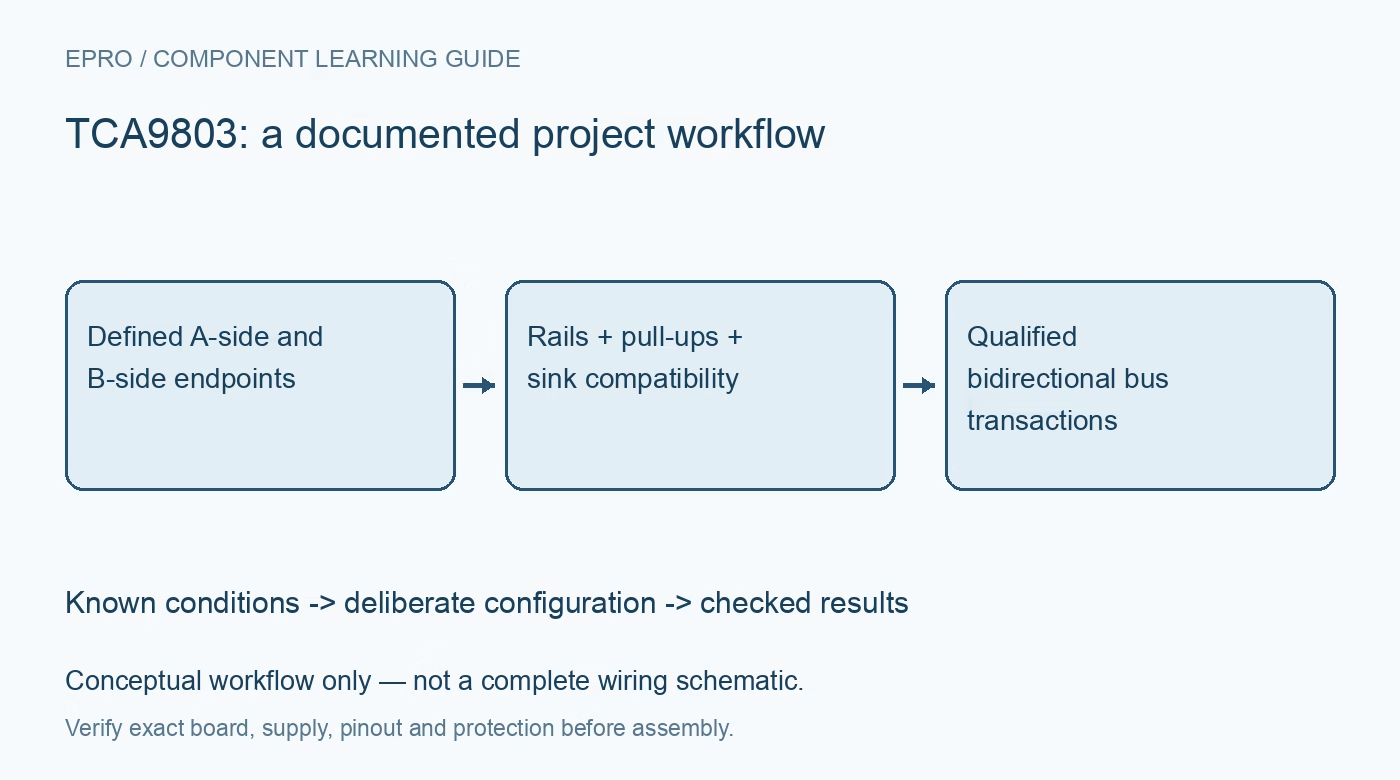
Review a TCA9803 bus by side, supply and sink-current compatibility, especially the internal B-side current source, before copying a standard pull-up arrangement. This is a documentation-based planning guide, not a report of independent hands-on testing.
1. Label both sides on the actual schematic
Identify which endpoints connect to side A and which connect to side B before reviewing voltage levels or pull-ups. The sides do not have interchangeable electrical roles, even though I2C data flow is bidirectional. Include every module and connector on the diagram, with its existing resistors and supply domain. A breakout-board label saying level shifter is not enough to establish compatibility with this particular active buffer or with the devices attached to it. Manufacturer documentation.
2. Check each supply against this device family
VCCA supports a different operating range from VCCB. For this family, VCCA can be above, below or equal to VCCB within the documented limits; do not copy a supply-ordering restriction from an unrelated repeater. Neither side should be treated as a universal five-volt interface. Check startup, shutdown and enable states as well as steady-state rails. Record the actual voltages seen by endpoint pins, especially when a connected module remains powered independently. Manufacturer documentation.
3. Do not add conventional B-side pull-ups
The B side uses an internal current source and is specified without external pull-up resistors on that side. Inspect breakout boards and endpoint modules for fitted pull-ups before connecting them. A familiar I2C wiring recipe can therefore be wrong for this design. The A side still needs its own appropriate pull-up arrangement. Review effective resistance, capacitance and rise time there, while following the separate manufacturer requirements on side B rather than treating both buses identically. Manufacturer documentation.
4. Verify low-state current compatibility
Recognition of an external B-side low depends on the endpoint meeting the documented sink-current and low-voltage conditions, not simply producing a voltage that looks low on a meter. Check the applicable IILC or equivalent sink-path requirements against the endpoint capability. Include series resistance and any additional active components in that path. A device that communicates successfully when directly connected to a passive bus may not automatically meet this buffer-specific interaction requirement. Manufacturer documentation.
Newest in the store


5. Review topology before cascading buffers
The absence of a static voltage offset does not make arbitrary buffer chains or mixed active-pull-up arrangements valid. Compare the intended topology, endpoint behavior and attached buffers with the manufacturer’s application guidance. Pay attention to which side of each device faces the other and how the resulting low-state current is established. Keep the initial test network simple. Add branches or additional buffering only after the basic transaction and release behavior are understood and documented. Manufacturer documentation.
6. Separate bus electrical health from protocol success
Check rise time, low level and clock stretching with representative bus loading and the selected clock rate. Then exercise complete reads and writes, including repeated starts where used by the application. An address acknowledgement alone is a narrow test. This buffer also does not solve two slaves sharing the same address, establish isolation or provide software recovery from every stuck-bus condition. Define those requirements separately instead of assigning them to the level-translation function. Manufacturer documentation.
7. Test power-state and fault recovery
Exercise host reset, endpoint reset, buffer enable changes and loss of each supply under controlled conditions. Observe whether the unpowered side affects the live bus, using the documented behavior rather than assumptions about generic translators. Keep bus traces, resistor inventory and rail states in the handover record. Confirm that recovery produces correct data, not just renewed acknowledgements. The final qualification applies to that endpoint combination and wiring, not to every module advertised as I2C compatible. Manufacturer documentation.
Related reading: TCA9617B I2C Repeater: 7 Checks for Compatible Buffered Lows.
Catalog note: The exact-part search did not return a matching Epro listing during preparation. Check the current catalog; this guide makes no price, availability or included-accessory claim.