


DRV8873 Motor Driver: 7 Checks for the Correct Interface and Current Path

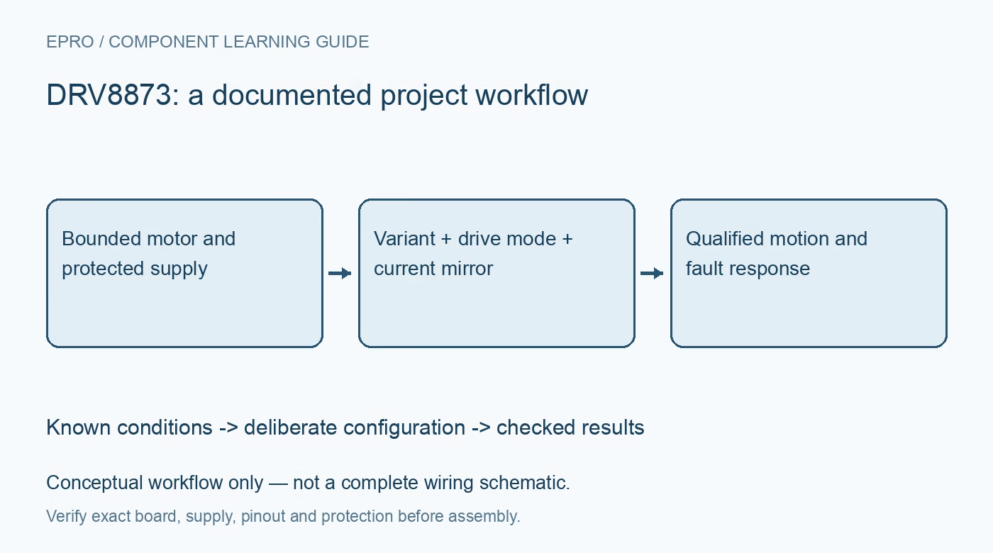
DRV8873 Motor Driver: 7 Checks for the Correct Interface and Current Path
Plan a DRV8873 motor stage around H or S configuration, high-side current mirrors, regulation limits and protected load-state tests before accepting feedback. This is a documentation-based planning guide, not a report of independent hands-on testing.
1. Distinguish hardware and SPI versions
Identify whether the assembly contains DRV8873H or DRV8873S. The H version uses hardware configuration, while the S version provides SPI configuration and diagnostics. A guide or library written for one should not be assumed to describe the other. Save the complete part marking, schematic and configuration method in the project record. Confirm the actual control-pin wiring before selecting a drive mode or expecting a diagnostic register to be available. Manufacturer documentation.
2. Bound the supply and mechanical system
Check the motor supply, expected startup and stall current, wiring and energy-storage components together. The device’s peak-current headline is not a continuous-current promise for a particular board, heatsink or ambient condition. Start with a current-limited protected supply and secure the motor mechanically. Keep fingers and loose objects away from the mechanism. Verify that the supply and protection arrangement can tolerate switching events and returned mechanical energy before attempting reversals or abrupt stops. Manufacturer documentation.
3. Document the selected input-control mode
The available control arrangements include PH/EN, PWM using IN1 and IN2, and independent half-bridge operation. Select the intended mode explicitly and follow its truth table for direction, drive, coast, brake and disabled states. Do not transfer pin-state assumptions between modes. Inspect the host pins during reset and boot, not just after the application starts. A software variable named enable does not establish which physical bridge state the configured device will actually produce. Manufacturer documentation.
4. Follow the high-side current-mirror path
IPROPI1 and IPROPI2 report current associated with the high-side FET paths. This is not the same sensing arrangement as every other driver in the family. Choose the external resistors and ADC input protection using the documented mirror relationship and limits. Identify which switching states make each observation meaningful. Keep settling, filtering and ADC sampling position in the analysis. A current-mirror voltage should not be treated as an unconditional instantaneous measurement of all motor current paths. Manufacturer documentation.
Newest in the store


5. Separate current regulation from fault protection
The device provides built-in current regulation using fixed-off-time operation. Its configuration differs by version, including selectable chopping settings for the SPI variant and the applicable fixed behavior for the hardware variant. Check that policy against the motor and thermal budget instead of assuming that regulation is absent or universally adjustable. Overcurrent and thermal protections are separate mechanisms. They do not establish a recommended continuous operating point or remove the need to choose a suitable motor and board. Manufacturer documentation.
6. Interpret diagnostics in the actual operating state
Review nFAULT and the diagnostics available on the fitted version for undervoltage, charge-pump, thermal, overcurrent and load-related conditions. For the SPI version, capture the relevant status before clearing or reinitializing it. Include the commanded bridge state and supply voltage in every fault record. Current feedback alone does not establish shaft position or prove a mechanically validated stall. A startup surge, disconnected load and constrained mechanism need deliberately different tests and response rules. Manufacturer documentation.
7. Qualify the complete motion sequence
Begin with a safe unloaded or lightly loaded mechanism and progress only within documented electrical and mechanical limits. Record direction changes, startup current, current-feedback waveforms, stop behavior and fault recovery. Evaluate slew-rate choices as an EMI and dissipation tradeoff rather than a free improvement. Repeat under representative load and supply conditions. The handover should connect commands to observed motion and fault outcomes, with clear limits on what was actually measured and no claim of independent device certification. Manufacturer documentation.
Related reading: DRV8876 Motor Driver: 7 Checks for Useful Current Feedback.
Catalog note: The exact-part search did not return a matching Epro listing during preparation. Check the current catalog; this guide makes no price, availability or included-accessory claim.