


SN74LVC1G123 One-Shot: 7 Checks for Retriggering and Clear-Release Pulses

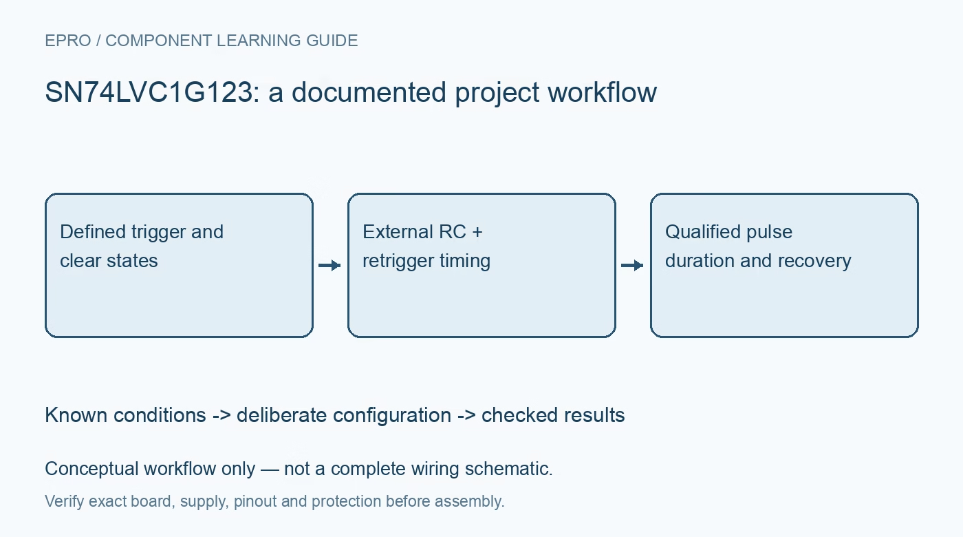
SN74LVC1G123 One-Shot: 7 Checks for Retriggering and Clear-Release Pulses
Qualify SN74LVC1G123 trigger conditions, retrigger extension, clear-release behavior and the correct external timing network. This is a documentation-based planning guide, not a report of independent hands-on testing.
1. Identify a retriggerable monostable, not a fixed timeout
The SN74LVC1G123 is a retriggerable one-shot operating from 1.65 to 5.5 volts. A qualifying event starts an output pulse whose basic duration is set by external timing components. Further qualifying events can extend that pulse, potentially maintaining a continuous active output. This makes it useful for pulse shaping, but unsuitable as an assumed maximum-on-time safety limit without a separate design assessment. Define the intended event rate, longest permitted output state and behavior when an input becomes noisy. Manufacturer documentation.
2. Document both gated trigger paths
A rising edge on B can trigger when A is held low. A falling edge on A can trigger when B is held high. These conditions are not equivalent to accepting every edge on either terminal. Choose one intended trigger path and establish the other input deliberately. The A and B inputs have Schmitt behavior, but hysteresis does not prevent every unwanted retrigger caused by a real threshold crossing. Review source levels and wiring noise against the device threshold specifications. Manufacturer documentation.
3. Include clear release in the trigger-state table
CLR low overrides the trigger inputs and can terminate an active pulse. However, when A is low and B is high, a rising transition on CLR is itself a valid trigger. A controller that releases clear after startup can therefore create a pulse even if the nominal event input has not just changed. Review clear assertion and release separately. Confirm that the surrounding circuit remains safe during both, rather than treating the clear pin as a passive administrative reset signal. Manufacturer documentation.
4. Connect the timing capacitor between its dedicated pins
The timing capacitor belongs between Cext and Rext/Cext, with the external resistor from Rext/Cext to VCC. It is not the generic resistor-and-capacitor-to-ground network used by every timer circuit. Follow the package drawing, capacitor polarity where relevant and layout guidance. Keep the timing node short and free of contamination. Add supply decoupling separately; a timing capacitor is not a substitute for a bypass capacitor. Inspect the actual footprint before assuming that similarly named pins are adjacent. Manufacturer documentation.
Newest in the store


5. Use characterized timing curves and valid component ranges
Pulse width depends on resistance, capacitance, supply and the timing constant described in the datasheet. TI provides an illustrative 1.8-volt application using ten kilohms and 0.1 microfarads for a nominal one-millisecond pulse; that example is not a universal precision equation for every supply. Account for capacitor tolerance, temperature behavior, leakage and resistor tolerance. Stay within recommended timing-component ranges. Define an acceptable pulse-width band instead of promising an exact duration from nominal component markings alone. Manufacturer documentation.
6. Respect minimum retrigger intervals and output loading
Not every arbitrarily close edge can be interpreted as a valid retrigger. Check the minimum retrigger-time conditions and timing curves for the selected supply and external network. Also budget propagation delay, clear pulse width and the load on Q or its complementary output. Avoid confusing the fast logic propagation headline with guaranteed accuracy of a long RC pulse. Capture trigger, clear and output together on one timebase to distinguish real extension from acquisition or trigger-display artifacts. Manufacturer documentation.
7. Test startup, burst events and deliberate early clear
Use a bounded logic-level source to check one event, a burst shorter than the nominal pulse, a sustained event stream and an early clear. Include clear release with every relevant A/B combination and controlled supply cycling. Save supply voltage, component values, input levels, load and observed pulse widths. Record expectations and measurements separately. The final acceptance criteria should show when the output may remain active indefinitely, rather than hiding retrigger behavior behind the reassuring but incomplete label of timer. Manufacturer documentation.
Related reading: SN74LVC1G14 Inverter: 7 Checks for Active-Low Schmitt Signal Paths.
Catalog note: The exact-part search did not return a matching Epro listing during preparation. Check the current catalog; this guide makes no price, availability or included-accessory claim.