


ADS7028 ADC: 7 Checks for RMS Windows, DC Subtraction and CRC Recovery

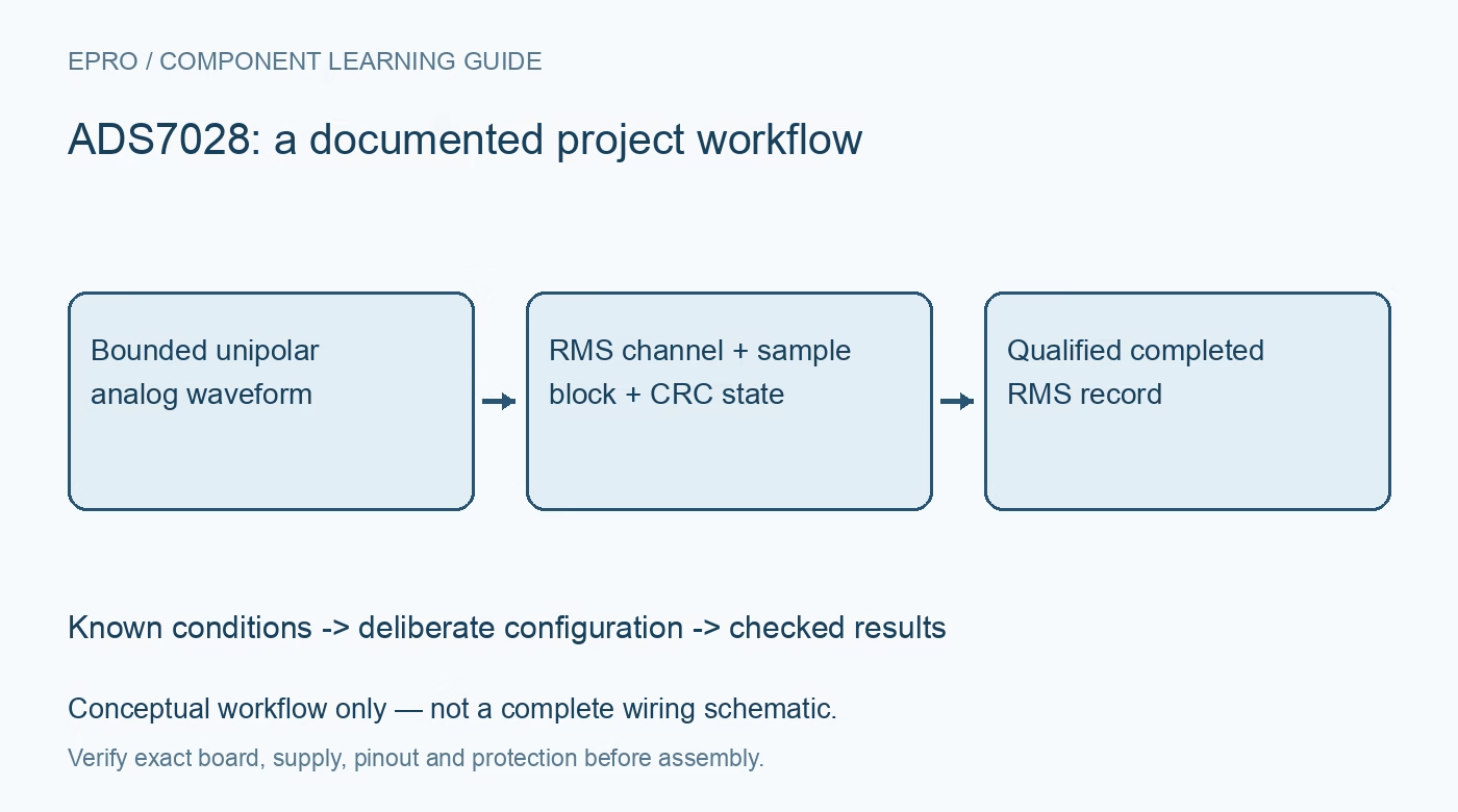
ADS7028 ADC: 7 Checks for RMS Windows, DC Subtraction and CRC Recovery
Configure ADS7028 RMS measurements with channel identity, sample-count windows, valid DC subtraction and deliberate CRC error recovery. This is a documentation-based planning guide, not a report of independent hands-on testing.
1. Identify the analog channel before enabling RMS
The ADS7028 combines an eight-channel multiplexed twelve-bit ADC with configurable GPIO functions and an RMS engine. A pin configured as a digital output is not simultaneously an ordinary analog measurement input. Record the pin-function map, analog supply and digital supply before starting acquisition. The analog supply range is 2.35 to 5.5 volts, while the digital supply range is 1.65 to 5.5 volts. Keep the waveform inside the permitted unipolar range; do not connect mains or an unprotected bipolar source directly. Manufacturer documentation.
2. Distinguish a sixteen-bit RMS result from ADC resolution
The RMS module produces a sixteen-bit numerical result from a block of twelve-bit ADC samples. That wider result does not turn every instantaneous conversion into a sixteen-bit measurement or guarantee sixteen-bit absolute accuracy. The RMS result scale is AVDD divided by 65536 per code under the documented convention. Reference variation, input conditioning, sample timing and noise still contribute error. Define whether the required result includes a DC component or represents only the alternating component before assigning engineering units to the returned number. Manufacturer documentation.
3. Set the sample block and actual elapsed window
Choose the RMS channel through RMS_CHID and the block size through RMS_SAMPLES. Available block sizes are 1024, 4096, 16384 and 65536 samples. These are counts of conversions on the selected analog channel, not universal millisecond windows. If a sequence visits other channels, the selected channel receives samples less frequently than the overall conversion stream. Derive the actual elapsed window from that channel cadence, and ensure the resulting interval covers the intended waveform behavior rather than assuming every block includes an exact number of cycles. Manufacturer documentation.
4. Apply DC subtraction only within its documented conditions
RMS_DC_SUB controls whether the DC component is subtracted from the RMS result. TI specifies that, when subtraction is enabled, the DC input level must remain within the documented five-percent tolerance around midscale. This is not arbitrary-offset removal for every unipolar waveform. Check the source bias, gain and clipping margin before enabling it. A valid numerical result can still be the wrong quantity if firmware confuses total RMS with AC-only RMS or if the external bias moves outside the permitted condition. Manufacturer documentation.
Newest in the store


5. Wait for completion and restart the block intentionally
Writing one to RMS_EN clears the RMS result registers and starts a new computation. The result is ready after the configured number of selected-channel samples has been converted. Poll RMS_DONE, or configure the documented RMS completion alert mapping, before accepting a new record. Starting another block requires another intentional write to RMS_EN. Store the channel, block count, DC-subtraction setting and completion time with each value. Reading a result register repeatedly does not prove that a fresh, continuously updated block has completed. Manufacturer documentation.
6. Implement CRC framing and fault clearing together
The optional interface CRC uses the CRC-8-CCITT polynomial x to the eighth plus x squared plus x plus one. Enabling it changes the transfer requirements for incoming and outgoing data; use the datasheet framing rather than appending an improvised checksum. When an incoming CRC error is detected, erroneous data are ignored and CRCERR_IN is set. Further register writes are disabled until that flag is cleared by writing one. Firmware must therefore include a deliberate recovery path, not merely log the error and retry ordinary configuration indefinitely. Manufacturer documentation.
7. Qualify a complete RMS record with known waveforms
Begin with safe, bounded DC levels and a low-voltage biased waveform from a suitable source. Verify channel assignment, block duration, DC-subtraction behavior and CRC recovery before trusting a reported RMS quantity. Check several amplitudes and frequencies within the actual acquisition bandwidth, noting any clipping or aliasing risk. Save raw configuration and actual observations separately from calculated expectations. This component-level test does not establish an isolated power meter or electrical-safety rating; any hazardous-voltage measurement system requires separately designed attenuation, isolation and protection. Manufacturer documentation.
Related reading: ADS7138 ADC: 7 Checks for Autonomous Window Alerts and Scan Timing.
Catalog note: The exact-part search did not return a matching Epro listing during preparation. Check the current catalog; this guide makes no price, availability or included-accessory claim.