


LM7705 Negative Bias Generator: 7 Checks for True-Zero Amplifier Headroom

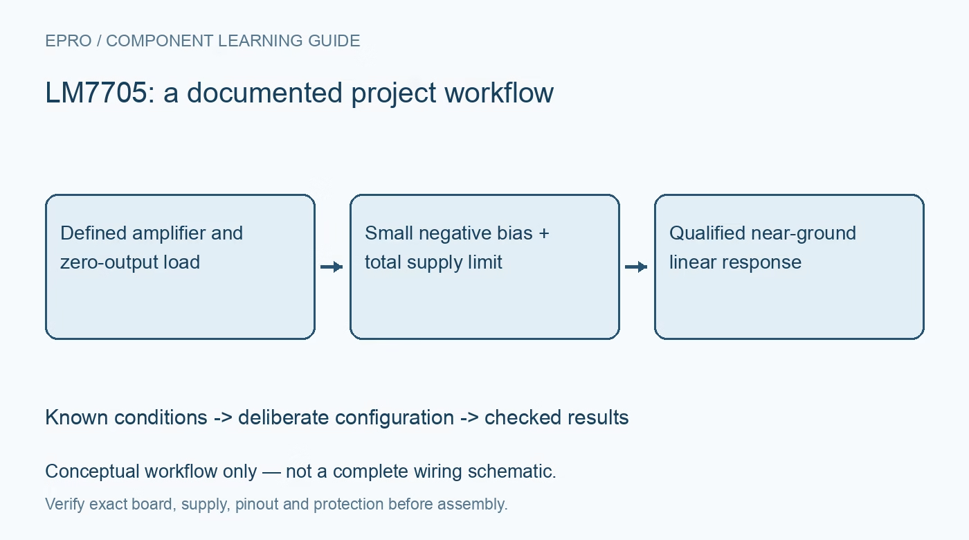
LM7705 Negative Bias Generator: 7 Checks for True-Zero Amplifier Headroom
Use LM7705 negative bias deliberately by checking amplifier total supply, current direction, capacitor roles, shutdown polarity and residual ripple. This is a documentation-based planning guide, not a report of independent hands-on testing.
1. Define why a small negative rail is needed
The LM7705 generates a fixed negative bias of approximately minus 0.232 volt to help a compatible amplifier produce a linear output at ground. It is not a general negative five-volt supply. An amplifier described as rail-to-rail can still require output headroom under load, so first identify the required zero-output current and the amplifier swing limits. Check whether a small negative supply actually addresses that limitation. Offset voltage, gain error and ADC behavior remain separate even if output saturation near ground is reduced. Manufacturer documentation.
2. Check both device input range and total amplifier supply
The generator operates from a three-to-5.25-volt supply under its documented conditions, with reduced performance toward the low end discussed in the datasheet. The amplifier sees the difference between its positive and negative rails. For example, five volts above ground and minus 0.232 volt below ground give a nominal total of 5.232 volts, not five volts. Include tolerances, startup and overshoot before comparing that total with the amplifier ratings. Also check all signal and reference pins against the amplifier negative rail. Manufacturer documentation.
3. Budget the negative rail in the correct current direction
The LM7705 is characterized for sinking current at its negative output, which is the relevant direction for many amplifier negative-supply loads. Do not treat a current capability headline as symmetric positive and negative load service. Add the amplifier operating current and output-dependent negative-rail demand, then compare with the regulation conditions in the electrical tables. TI discusses load regulation up to twenty milliamps; that is not a promise of the same output voltage at every larger transient or every input voltage. Manufacturer documentation.
4. Keep flying, reservoir and output capacitors distinct
The switched-capacitor inverter uses external flying and reservoir capacitors, followed by regulation and an output capacitor. These components occupy different terminals and perform different functions. Follow the manufacturer application circuit and package drawing rather than substituting one capacitor to ground for the complete network. Check effective capacitance, voltage stress, polarity where relevant and placement. Keep switching loops compact and away from sensitive amplifier inputs. A correct DC output on a meter does not establish low ripple or stable transient behavior. Manufacturer documentation.
Newest in the store


5. Use the actual shutdown polarity and startup sequence
SD low enables the LM7705; SD high turns it off. This active-high shutdown function is easy to confuse with an active-high enable. Define its controller state during reset and partial power, using the specified input thresholds. Plan when the amplifier may begin accepting a signal relative to the negative rail becoming valid. The advertised turn-on behavior belongs to stated test conditions, not every populated load and capacitor combination. Verify recovery rather than assuming that toggling shutdown leaves the whole signal chain immediately settled. Manufacturer documentation.
6. Treat switching ripple as a system-level error source
The charge pump necessarily transfers charge in pulses, and output ripple depends on load and external capacitance. A low-noise headline does not mean the negative rail is spectrally empty. Check how amplifier supply rejection varies with frequency and whether residual components can reach an ADC or mix with its sample timing. Observe the negative rail and amplifier output with appropriate probing. Keep switching-current return paths separate from sensitive reference routing, and assess a realistic measurement bandwidth rather than only an averaged multimeter reading. Manufacturer documentation.
7. Verify zero-output linearity under the intended load
Use a current-limited low-voltage setup and compare small commanded output levels around ground while observing the negative rail, total amplifier supply and output load. Check startup, shutdown and the largest relevant output-current transition. Record the amplifier model, capacitor network, load, supply tolerances and actual settling behavior. Separate observations from manufacturer expectations and calculations. A successful near-zero demonstration does not prove zero offset, universal ADC compatibility or operation outside any amplifier input, output or total-supply rating. Manufacturer documentation.
Related reading: LM27762 Dual Rails: 7 Checks for Headroom, Enables and PGOOD.
Catalog note: The exact-part search did not return a matching Epro listing during preparation. Check the current catalog; this guide makes no price, availability or included-accessory claim.