


ADS131A04 Simultaneous ADC: 7 Checks for Startup Straps, Frames and CRC

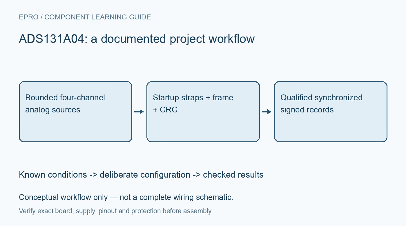
ADS131A04 Simultaneous ADC: 7 Checks for Startup Straps, Frames and CRC
Plan ADS131A04 acquisition with startup-latched word lengths, simultaneous channels, signed codes, frame integrity and verified configuration. This is a documentation-based planning guide, not a report of independent hands-on testing.
1. Start with a safe analog envelope
ADS131A04 provides four simultaneous delta-sigma conversion channels, but the inputs still need conditioning and protection appropriate to the selected supplies. Check each pin voltage and common-mode condition as well as the differential signal. The internal negative charge-pump option has its own narrower analog-supply requirements; it is not permission for unlimited negative inputs. Begin with protected, low-voltage sources. An energy-metering application diagram is not a safe instruction to connect a controller board directly to mains wiring. Manufacturer documentation.
2. Record the startup-latched interface straps
M1 selects the device word length at power-up: high selects 32 bits, low selects 24 bits and floating selects 16 bits under the documented connections. Changing the pin afterward does not change the latched setting. M0 and M2 also participate in interface configuration, so include all strap states in the board record. Match firmware parsing to the actual hardware configuration rather than a library default. A shifted-looking conversion word can originate from a word-length mismatch instead of analog noise. Manufacturer documentation.
3. Complete the reset and unlock exchange
Use the documented power-on or reset status exchange before sending configuration writes. The device begins in a locked state; the UNLOCK command is 0x0655, and command responses must be interpreted with the specified frame timing. Confirm that the expected status arrives and read configuration back after writing it. Avoid treating a successful SPI transfer call as proof that the ADC accepted the command. Keep reset handling repeatable so a recovered device returns to the same known acquisition state. Manufacturer documentation.
4. Define the entire frame, not just channel bytes
In fixed-frame mode, ADS131A04 uses six device words: status, four channel-data words and a final CRC position. Dynamic-frame length depends on enabled channels and CRC configuration. Decide the format explicitly and generate the complete required number of clocks, including positions that carry padding rather than useful data. Account for command-response timing separately from conversion timing. Store channel order with the frame definition so disabling a channel cannot silently relabel all subsequent values in the acquisition software. Manufacturer documentation.
Newest in the store


5. Implement integrity checks for the selected mode
The interface offers CRC and Hamming-code options, but these must match the selected word length, strap state and frame configuration. The documented CRC uses the CRC-CCITT polynomial; polynomial identity alone does not specify every byte-coverage and padding rule. Build test vectors from the actual framing mode and verify both valid and deliberately corrupted records. Note the special WREGS behavior: CRC errors can be indicated after registers have been written. Read back critical configuration rather than assuming every bad write was automatically rejected. Manufacturer documentation.
6. Decode signed data with the correct scale
Conversion data is binary two’s complement, transmitted most significant bit first, with the precise useful-data width determined by configuration. Remove padding or integrity fields before sign extension and apply the reference-dependent conversion scale from the datasheet. Test zero differential input and known positive and negative stimuli. The 24-bit headline does not promise 24 noise-free bits at every data rate. Include reference uncertainty, source settling, analog filtering and the selected digital-filter conditions when interpreting apparent resolution. Manufacturer documentation.
7. Preserve timing and quality with each record
Simultaneous channels support meaningful cross-channel timing, but timestamps, filter delay and missed-frame handling still belong in the acquisition design. Record data rate, reference configuration, enabled-channel map, raw words, integrity result and relevant status bits. Reject or explicitly flag invalid frames instead of smoothing them into a plausible trace. Test reset recovery and bounded input steps at the intended throughput. This produces a reproducible qualification record; it does not turn a documentation-based example into a measured accuracy or phase-performance claim. Manufacturer documentation.
Related reading: ADS131E08 ADC: 7 Checks for Rate-Dependent Frame Length.
Catalog note: The exact-part search did not return a matching Epro listing during preparation. Check the current catalog; this guide makes no price, availability or included-accessory claim.