


TPS7A94 Low-Noise LDO: 7 Checks for NR/SS Voltage Setting and PG Coupling

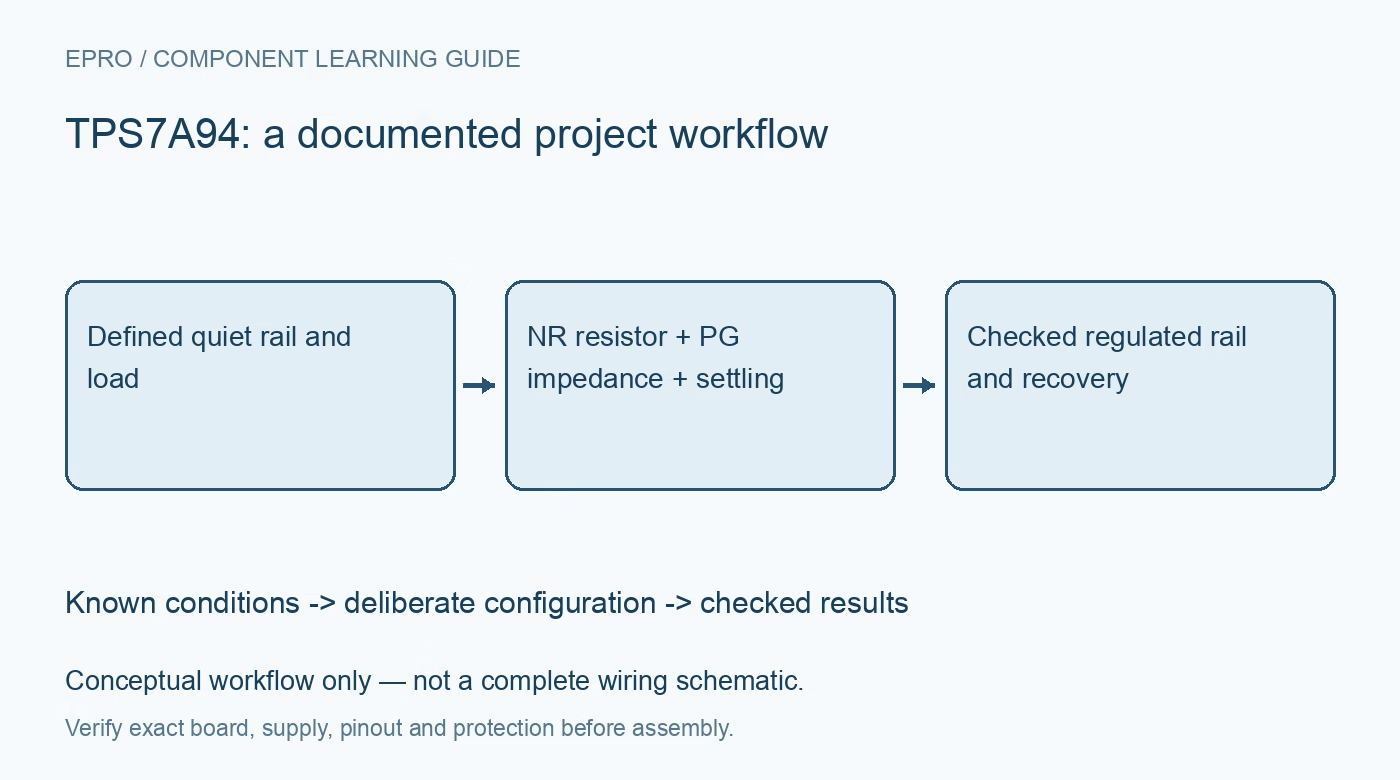
TPS7A94 Low-Noise LDO: 7 Checks for NR/SS Voltage Setting and PG Coupling
Plan TPS7A94 rails with current-source output programming, coupled power-good and current-limit settings, capacitor constraints and realistic settling. This is a documentation-based planning guide, not a report of independent hands-on testing.
1. Check the recommended voltage envelope
The TPS7A94 input range is 1.7V to 5.7V. Its recommended operating table specifies an output minimum of 0.4V and a maximum constrained by input voltage minus required dropout, even though broader feature descriptions mention operation toward zero. Use the operating and accuracy tables for the actual design target. The 1A headline is subject to thermal and electrical limits. Establish a feasible input-output pair with source tolerance and load transients included, rather than selecting voltages from headline ranges independently. Manufacturer documentation.
2. Program voltage with the NR/SS resistor
This regulator uses an internal current source and a resistor from NR/SS to ground to establish output voltage. The documented relationship is output voltage equals the NR/SS current multiplied by that resistor, not the usual fixed-reference feedback-divider equation. With the typical 150-microamp current, 22 kilohms corresponds nominally to 3.3V. Treat that as a planning calculation and include current accuracy and resistor tolerance. Connect the separate SNS pin according to the manufacturer layout and sensing guidance. Manufacturer documentation.
3. Do not leave FB_PG floating
FB_PG is required for proper operation even if the digital PG indication is not used. Its divider sets the power-good threshold, while the parallel impedance of the same divider is sampled during initialization to select a current-limit scale. The two functions are coupled. Choose both resistor values using the documented procedure, not just their ratio. A divider substitution that preserves the threshold ratio can still alter current-limit behavior. Record the actual fitted values and verify the startup configuration after any board revision. Manufacturer documentation.
4. Distinguish current-limit scales from precision limiting
The documented settings select 100%, 80% or 60% of the factory-programmed nominal current limit, subject to the stated impedance bands and output-voltage conditions. These are protective operating characteristics, not a precision programmable current source. The lower-current settings also constrain the allowed PG threshold choices. Keep nominal values, tolerances and protection behavior separate from the normal load budget. Validate the intended operating load using a protected source rather than planning to run continuously at the point where protection engages. Manufacturer documentation.
Newest in the store


5. Meet capacitor and loop-impedance requirements
The recommended table specifies minimum input and output capacitance, an NR/SS capacitor range, output-capacitor ESR and a very low output-loop inductance target. Placement and effective capacitance therefore matter as much as printed values. Follow the layout guidance with short current loops and a quiet NR/SS ground connection. An arbitrary breakout board or long wire harness can lose the conditions behind the low-noise headline. Review DC-bias derating and the selected capacitor network before drawing conclusions from a startup or load-step waveform. Manufacturer documentation.
6. Allow precision settling beyond the initial ramp
NR/SS capacitance reduces noise and shapes startup, while the internal fast-start behavior changes as the rail approaches its target. Do not estimate the entire settling interval from one constant-current ramp alone. Observe output voltage and PG together at the required accuracy. Adequate headroom is also essential: operating near dropout degrades PSRR and transient response even at loads that appear modest. Include brownout and recovery behavior in the qualification rather than treating a nominally correct DC output as the complete result. Manufacturer documentation.
7. Measure noise and heat under defined conditions
The sub-microvolt noise headline refers to a specified integration bandwidth and circuit conditions. Use suitable measurement equipment, bandwidth control and grounding before comparing a real rail with that number. Estimate pass loss from voltage drop multiplied by current and verify temperature at the intended load. Record supply, NR/SS resistor and capacitor, PG-divider values, output network, headroom and load. Report measured noise, settling and thermal behavior separately so the handover distinguishes actual evidence from documentation-based expectations. Manufacturer documentation.
Related reading: TPS7A91 Low-Noise LDO: 7 Checks for Soft Start and Power-Good Timing.
Catalog note: The exact-part search did not return a matching Epro listing during preparation. Check the current catalog; this guide makes no price, availability or included-accessory claim.