


DRV5056 Hall Sensor: 7 Checks for Unipolar Fields and Split Supply Bands

DRV5056 Hall Sensor: 7 Checks for Unipolar Fields and Split Supply Bands
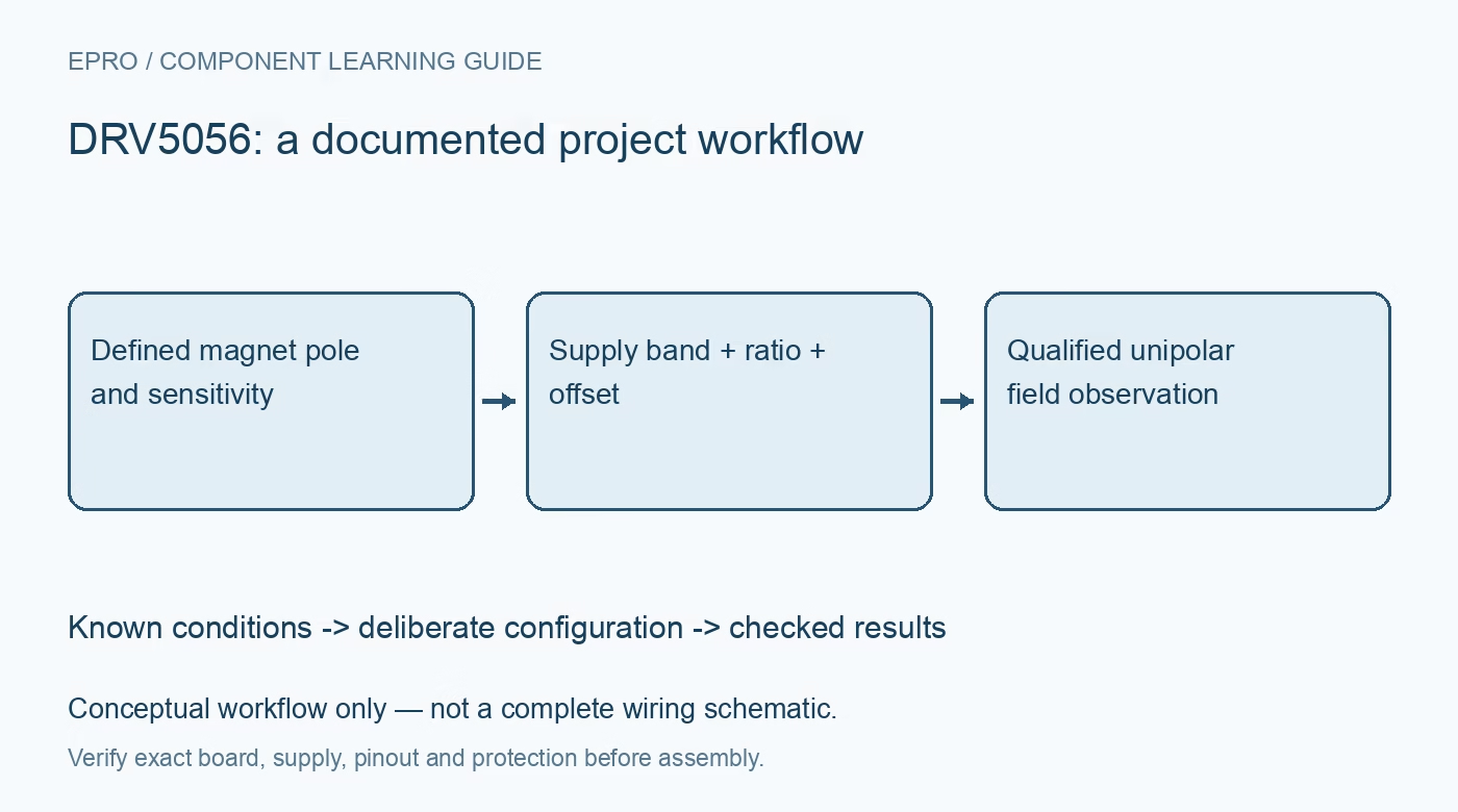
Use DRV5056 with the correct south-pole response, sensitivity suffix, isolated supply ranges, ratiometric conversion and magnet calibration. This is a documentation-based planning guide, not a report of independent hands-on testing.
1. Start with the unipolar field response
DRV5056 is a unipolar linear Hall sensor intended for the documented south-pole field direction, not a symmetric positive-and-negative field instrument. Its output begins near a 0.6V quiescent offset and increases with the intended magnetic stimulus. Confirm the package sensitive axis and magnet orientation before changing software signs. A magnet presented with the opposite pole cannot be interpreted simply by extending the same linear equation below zero. Record the complete device suffix and the mechanical orientation in the fixture. Manufacturer documentation.
2. Respect the two isolated supply ranges
The recommended VCC bands are 3V to 3.6V and 4.5V to 5.5V. They are not one continuous 3V-to-5.5V specification. The manufacturer explains that a crossover region near 4V makes sensitivity less known in the intermediate range. A directly connected lithium-cell rail can pass through that region, so choose a suitable regulated supply rather than assuming all battery voltages are equivalent. Include startup and brownout in the rail assessment and flag data collected outside the specified operating bands. Manufacturer documentation.
3. Match sensitivity and temperature option
Sensitivity differs across A1, A2, A3, A4, A6, A8 and the documented Z alternatives. A-series and Z-series versions also differ in magnet-temperature compensation behavior. Do not apply a nominal sensitivity quoted at 5V unchanged to every suffix and supply condition. The A6 operating-temperature range is additionally narrower than the other listed options. Identify the exact version, select the corresponding electrical table and preserve those limits with the configuration before calculating field or claiming temperature stability. Manufacturer documentation.
4. Use ratiometry without hiding offset error
The sensitivity scales with supply voltage, allowing an ADC that uses the same supply as its reference to reduce some supply-tolerance effects. That benefit does not eliminate offset, sensitivity tolerance, noise or reference-routing error. Keep the output baseline and sensitivity model distinct and use the documented behavior for the actual supply band. Verify that the controller ADC input remains within its own voltage limits. A 5V-powered sensor cannot be connected blindly to a 3.3V-only converter simply because the calculation is described as ratiometric. Manufacturer documentation.
Newest in the store


5. Keep the output in its usable range
Check output swing and loading against the datasheet, including the ADC sampling network and any external filter. A reading near a rail may indicate saturation rather than an unusually large valid field. Begin with a controlled weak field and increase it within a bounded fixture. Save raw output voltage or ADC codes alongside converted field values so clipping and baseline movement remain visible. Do not smooth saturated readings into an apparently continuous position curve that conceals the sensor range limit. Manufacturer documentation.
6. Calibrate position with the actual magnet
Magnetic field depends on magnet material, dimensions, pole orientation, lateral offset, air gap and nearby steel. Converting field to distance therefore requires a geometry-specific calibration, not a universal inverse formula. Use known positions and repeatable fixtures, then preserve the valid interpolation range. Temperature compensation is designed around magnet behavior and is not a guarantee for every magnet assembly. Recheck the calibration whenever the magnet, mounting, sensor orientation or surrounding ferromagnetic parts change. Manufacturer documentation.
7. Record timing and uncertainty with results
Choose sampling and filtering that match the documented sensor response and the motion being measured. Check startup settling, noise, repeated approach direction and return-to-position behavior. Log supply band, exact suffix, magnet geometry, temperature, raw samples and any saturation or invalid-supply flags. Keep the uncertainty of the mechanical reference separate from electrical conversion error. This produces evidence for a defined fixture and operating range rather than claiming that every DRV5056 board measures distance accurately without application-specific qualification. Manufacturer documentation.
Related reading: DRV5053 Analog Hall Sensor: 7 Checks for Sensitivity Sign and Output Loading.
Catalog note: The exact-part search did not return a matching Epro listing during preparation. Check the current catalog; this guide makes no price, availability or included-accessory claim.