


DRV5053 Analog Hall Sensor: 7 Checks for Sensitivity Sign and Output Loading

DRV5053 Analog Hall Sensor: 7 Checks for Sensitivity Sign and Output Loading
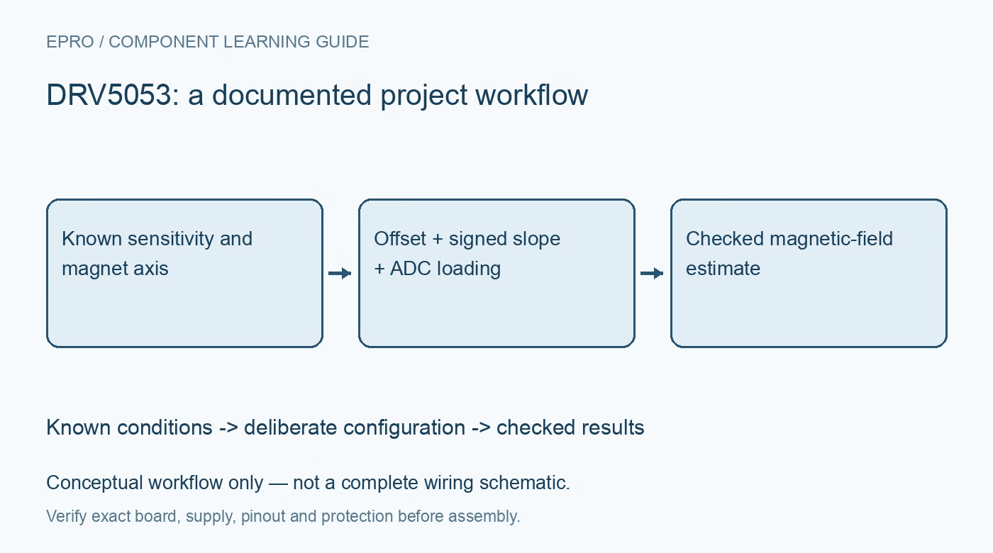
Use DRV5053 with the correct sensitivity suffix, approximately 1V zero-field output, ADC loading and calibrated magnet geometry. This is a documentation-based planning guide, not a report of independent hands-on testing.
1. Read the sensitivity suffix first
DRV5053 is a linear analog Hall sensor with multiple sensitivity options. Some suffixes have negative slopes and others positive slopes, so reversing the software sign without identifying the device is not a reliable calibration method. Read the complete ordering code and use its sensitivity table, tolerance and temperature conditions. Confirm the package pinout separately for the surface-mount or through-hole version. A visually similar sensor can have different terminal ordering or a completely different output type. Manufacturer documentation.
2. Use the approximately 1V zero-field baseline
The quiescent output is around 1V, not automatically half of the supply rail. The documented output span is approximately 0.2V to 1.8V, subject to operating conditions. Do not convert the output using a ratiometric half-supply formula copied from another Hall sensor. Establish a zero-field baseline in the final fixture, recognizing that nearby steel and ambient magnetic fields can affect it. Record the actual baseline and its uncertainty instead of forcing every sensor reading to equal exactly one volt. Manufacturer documentation.
3. Respect the electrical operating range
The recommended supply range is 2.5V to 38V, but the controller ADC and other board components may have much lower limits. Check the sensor supply, output connection and common reference independently. Reverse-supply and load-dump protection statements do not replace the recommended operating conditions or certify an entire module. Use a current-limited supply and local bypassing for initial checks. Verify ground continuity before connecting the analog output to a controller that may be powered through another cable. Manufacturer documentation.
4. Budget the asymmetric output drive
The output stage has different source and sink capabilities: the feature summary lists about 300 microamps sourcing and 2.3mA sinking. A low-resistance load or a large sampling-current transient can therefore distort the voltage even though it remains within the ADC input range. Review the converter acquisition network and sensor capacitive-load guidance together. Use a suitable buffer when the load requires it, then qualify settling. A high-impedance multimeter reading alone cannot prove compatibility with a switched-capacitor ADC input. Manufacturer documentation.
Newest in the store


5. Convert field using offset and signed slope
Use a model such as field equals measured output minus the established zero-field output, divided by the signed sensitivity. Keep units consistent: millivolts per millitesla must not be mixed silently with volts or tesla. As an illustration, a 100mV change divided by a nominal minus-23mV/mT sensitivity represents about minus 4.35mT before calibration and tolerances. This is a calculation example, not measured performance. Reject values near clipping rather than extending a linear formula beyond the usable range. Manufacturer documentation.
6. Control magnet orientation and geometry
The sensor measures the field component along its sensitive axis, not distance directly. Magnet grade, pole direction, air gap, lateral offset, temperature and nearby ferromagnetic material all affect the transfer. Build a stable fixture and log the mechanical dimensions alongside the voltage. If distance is required, calibrate that specific geometry against known positions and preserve the valid range. Flipping a magnet or changing its diameter can invalidate an earlier distance curve even if the electronics and sensor sensitivity remain unchanged. Manufacturer documentation.
7. Characterize timing and repeatability
The documented bandwidth and startup characteristics are conditional device specifications, not proof of the complete acquisition rate. Choose sampling and filtering that preserve the signal of interest, and avoid treating averaged samples as independent high-speed observations. Log supply, temperature, baseline, raw ADC values and any clipping flags during repeated bounded movements. Compare returning to the same position from both directions to reveal fixture or magnetic effects. Report the tested configuration and uncertainty rather than presenting a generic sensor conversion as a universal position measurement. Manufacturer documentation.
Related reading: DRV5057 PWM Hall Sensor: 7 Checks for Duty Cycle, Supply Bands and Magnet Geometry.
Catalog note: The exact-part search did not return a matching Epro listing during preparation. Check the current catalog; this guide makes no price, availability or included-accessory claim.