


TMUX1121 Analog Switch: 7 Checks for Independent Channels and Leakage

TMUX1121 Analog Switch: 7 Checks for Independent Channels and Leakage
Use TMUX1121 dual SPST channels deliberately: verify active-high control, signal bounds, leakage, charge injection and settling. This is a documentation-based planning guide, not a report of independent hands-on testing.
1. Recognize two independent SPST paths
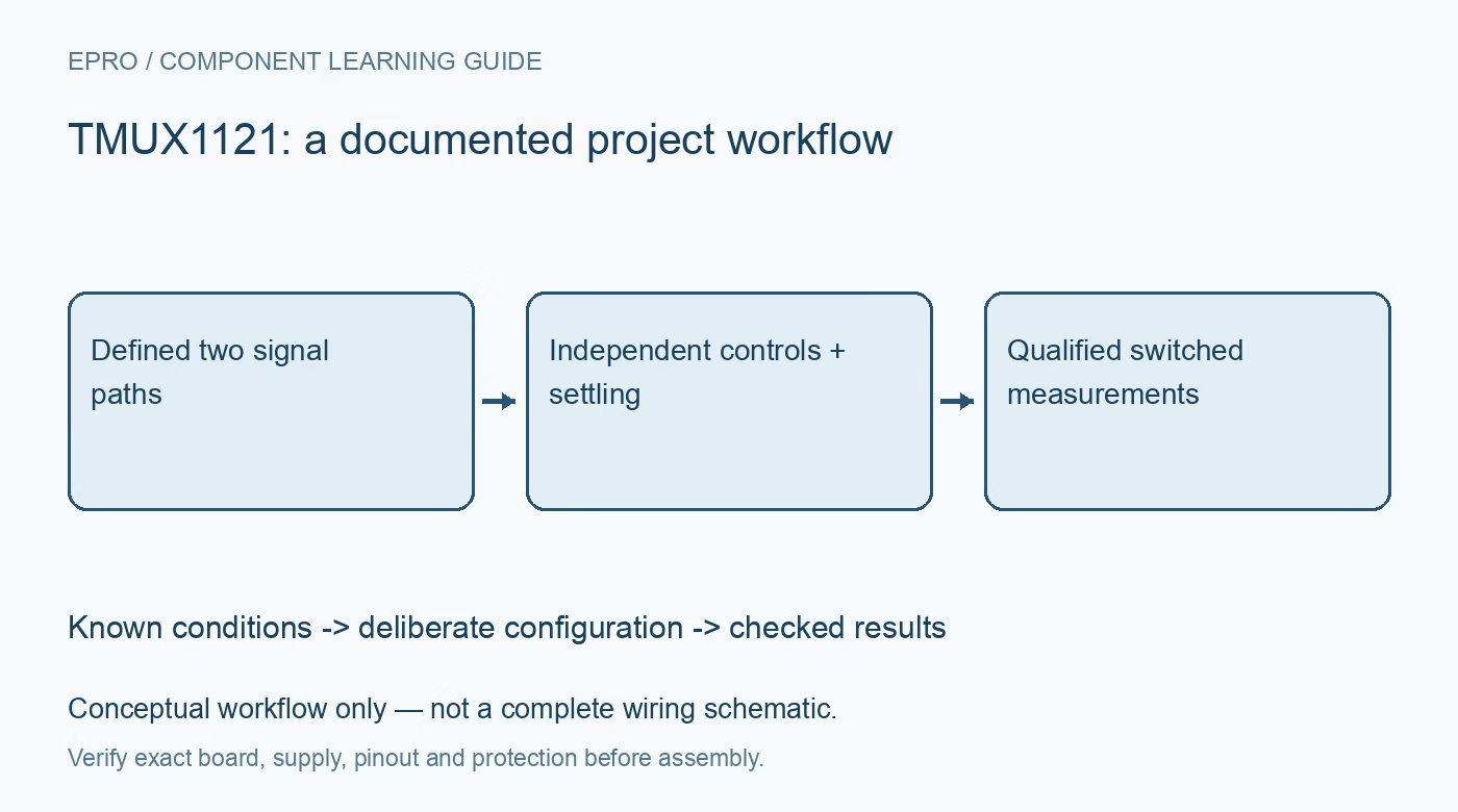
TMUX1121 contains two independently controlled single-pole, single-throw switches. It is not a two-input selector with one common output. Draw each source-to-drain connection and identify which control belongs to it. Both paths may be enabled together, or both disabled, depending on their independent logic levels. If external wiring joins separate voltage sources, simultaneous enable can create contention. The integrated switch arrangement does not automatically arbitrate between competing signal generators. Manufacturer documentation.
2. Keep analog signals within the supply rails
The operating supply range is 1.08 V to 5.5 V, and the analog signal paths support voltages from ground to VDD under the documented conditions. A negative sensor signal or an input above VDD needs an appropriate interface. Fail-safe logic applies to the control inputs and must not be generalized into powered-off analog protection. Review the electrical limits for source, drain and supply independently before connecting a signal that can remain powered. Manufacturer documentation.
3. Initialize both active-high controls deliberately
For TMUX1121, a logic one enables the corresponding path and a logic zero disables it. The related TMUX1122 has different control polarity, so family familiarity is not enough. Configure reset-state pull resistors and controller boot behavior for both pins. The manufacturer recommends defined unused logic levels rather than floating controls. Test all four control combinations with bounded sources and record the resulting connectivity before relying on a more complicated acquisition sequence. Manufacturer documentation.
4. Budget resistance as a signal-dependent error
On-resistance adds to the source and load network. The headline low resistance is not a universal constant across every voltage and temperature. For a loaded signal path, calculate the divider error using the relevant limits and the receiving input resistance. For a capacitor input, include the added resistance in acquisition settling. A high-impedance voltmeter can show little static loss while the same circuit still fails to settle during a short sampling interval. Manufacturer documentation.
Newest in the store


5. Account for leakage at the actual source impedance
Leakage becomes important when the source impedance is high or a capacitor must retain charge. Use the appropriate on-state and off-state limits at the intended temperature, rather than a room-temperature typical figure alone. As an error-budget illustration, leakage multiplied by source resistance gives an approximate voltage error for a resistive source. Include board contamination, connector leakage and instrument input current. Their contribution can exceed the switch contribution in a poorly controlled prototype. Manufacturer documentation.
6. Allow charge injection and settling to become visible
Changing a control can disturb a high-impedance node through charge injection and parasitic coupling. A useful first estimate is voltage disturbance approximately equal to injected charge divided by node capacitance, but the actual transient depends on the complete network. Observe the selected signal after each transition and choose a justified acquisition delay. Independent controls do not provide a guaranteed break-before-make sequence between externally interconnected channels; implement required dead time explicitly in the system. Manufacturer documentation.
7. Validate each state with representative loading
Check both channels on and off, then repeat transitions with the actual receiver, cables and filtering present. Include power sequencing and controller reset while keeping analog pins within their permitted conditions. Log supply voltage, control levels, source impedance, temperature and the delay before reading. Distinguish off-state feedthrough from a valid measurement. This evidence supports a bounded switching design without treating an open path as safety isolation or claiming unmeasured precision. Manufacturer documentation.
Related reading: TMUX1119 Precision Switch: 7 Checks for Leakage, Charge Injection and Settling.
Catalog note: The exact-part search did not return a matching Epro listing during preparation. Check the current catalog; this guide makes no price, availability or included-accessory claim.