


LP5018 LED Driver: 7 Checks for Package Mapping and IREF Current

LP5018 LED Driver: 7 Checks for Package Mapping and IREF Current
Plan LP5018 lighting with exact package mapping, IREF current selection, bank ownership, dimming controls and thermal checks. This is a documentation-based planning guide, not a report of independent hands-on testing.
1. Start with the exact package, not just eighteen outputs
LP5018 is an eighteen-channel constant-current sink driver, but the available package versions do not share a simple one-to-one mapping between physical output numbers and every internal color register. Compare the actual RSM or DGS pin diagram and the bank-assignment table with the PCB. Build a mapping from connector, LED color, physical output and register address. Eighteen channels can support six RGB groups in a straightforward arrangement, but that grouping must not be assumed across package variants. Manufacturer documentation.
2. Calculate the IREF resistor and verify its connection
A single external IREF resistor sets the global current scale. The datasheet gives RIREF equal to KIREF multiplied by VIREF and divided by the desired current, with nominal KIREF of 105 and VIREF of 0.7 V. Apply resistor tolerance and device current accuracy when planning a safe setting. Leaving IREF floating produces nearly zero output current; shorting it is not the normal way to select a desired LED current. Confirm the resistor on the assembled board. Manufacturer documentation.
3. Match the maximum-current option to VCC and the LEDs
The specified VCC range is 2.7 V to 5.5 V. The 25.5 mA maximum-current option covers that range, while the 35 mA option requires at least 3.3 V VCC. These settings do not override LED current ratings, output compliance or package thermal limits. Check anode voltage and LED forward voltage independently of VCC. A high supply voltage can increase driver dissipation even when each LED current remains within its own permissible range. Manufacturer documentation.
4. Separate physical pin mapping from bank ownership
Independent color and brightness registers apply only when the corresponding group is not assigned to bank control. In bank mode, bank color and brightness govern the selected outputs. This distinction becomes especially important with package-specific assignments: writing the register suggested by a connector number may affect a different output or no bonded output. Use a one-channel diagnostic pattern and a recorded mapping table before enabling shared bank effects or a full animation sequence. Manufacturer documentation.
Newest in the store


5. Preserve register width and dimming-mode assumptions
The device combines eight-bit color and brightness controls with an internal twelve-bit, nominal 29 kHz PWM implementation. Twelve-bit internal modulation does not mean that each host color register accepts twelve-bit data. Choose linear or logarithmic brightness behavior deliberately and retain that selection with the animation configuration. Compare a known code ramp under fixed optical conditions. Camera auto-exposure and varying ambient light can make a correct register sequence look nonlinear or inconsistent. Manufacturer documentation.
6. Establish addresses, enable and low-power transitions
Do not leave either address-selection pin floating. Verify their actual levels, the selected I2C address, EN and the chip configuration after reset. Broadcast commands deserve special care on a bus containing multiple compatible drivers. Automatic power saving is conditional on its configuration and the outputs remaining inactive for the documented period; it differs from EN-controlled shutdown. Measure board consumption separately from any LED-anode supply and external pull-ups before comparing it with bare-device current specifications. Manufacturer documentation.
7. Qualify the package map with light and temperature evidence
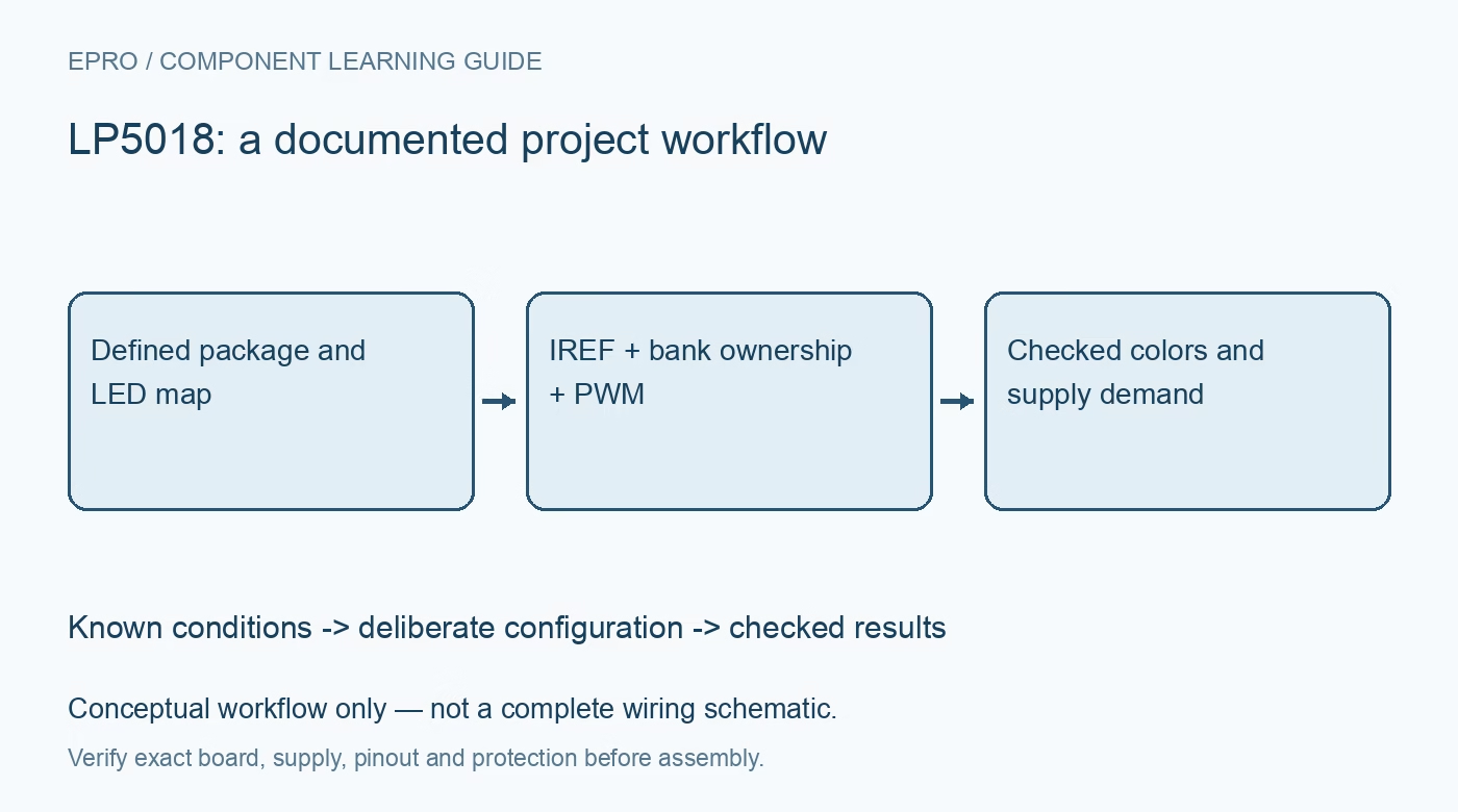
Begin with low current and activate each bonded output individually, saving the physical color and register association. Then test bank ownership, brightness ramps and simultaneous loading while watching rail droop and temperature. Exercise controller reset and power restoration with an intentional dark default. Record package marking, IREF resistance, current option and output map alongside observations. This documentation-based method supports reproducibility without claiming that an attractive animation proves electrical compliance or that the conceptual diagram is a complete schematic. Manufacturer documentation.
Related reading: LP5012 RGB LED Driver: 7 Checks for Bank Ownership and Dimming.
Catalog note: The exact-part search did not return a matching Epro listing during preparation. Check the current catalog; this guide makes no price, availability or included-accessory claim.