


TPS7A88 Dual LDO: 7 Checks for Shared Heat and Independent Startup

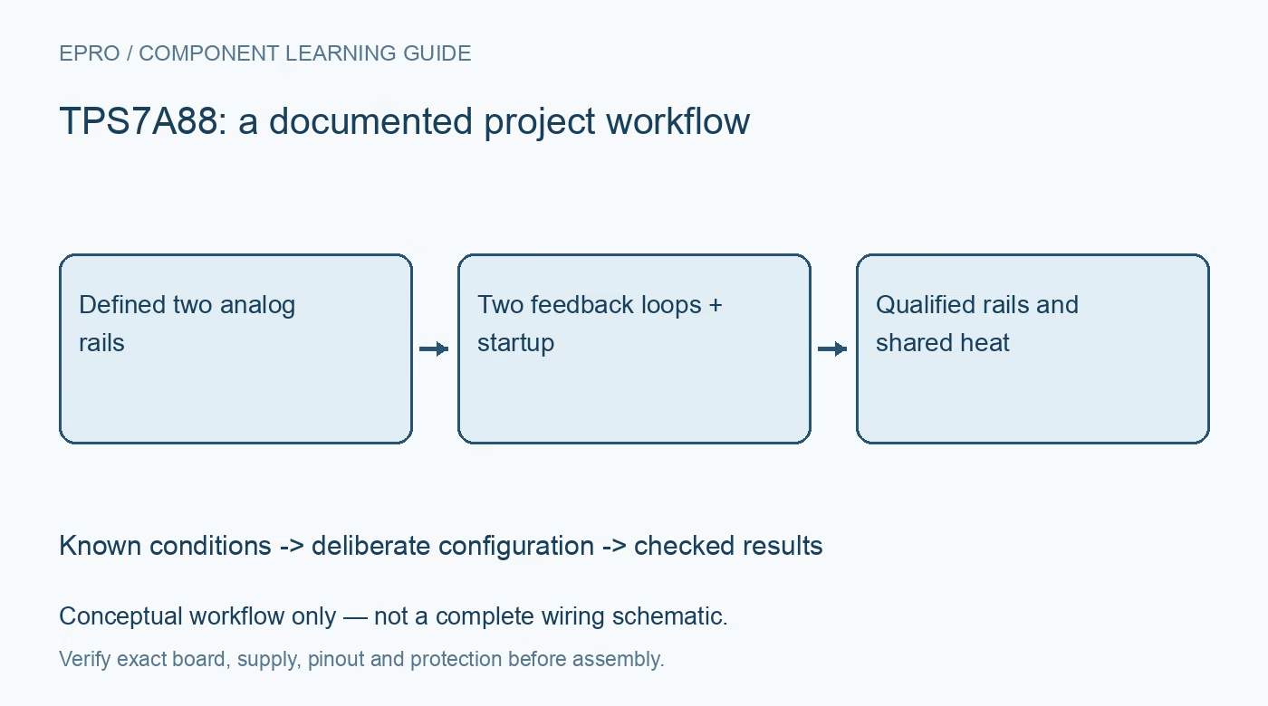
TPS7A88 Dual LDO: 7 Checks for Shared Heat and Independent Startup
Review TPS7A88 dual-channel regulation, individual soft-start controls, capacitor requirements, power-good signals and combined dissipation. This is a documentation-based planning guide, not a report of independent hands-on testing.
1. Identify two complete regulators in one package
TPS7A88 contains two independently controlled low-noise LDO channels, each capable of sourcing up to 1 A under the specified conditions. Trace the separate input, output, feedback, enable, noise-reduction and power-good connections for each channel. Independence of control does not mean separate thermal packages or complete system isolation. Establish which downstream circuits connect the rails through signals or protection diodes before choosing startup order. Keep the package orientation and exposed-pad implementation in the schematic review. Manufacturer documentation.
2. Select each operating point within its own headroom
The documented input range is 1.4 V to 6.5 V and adjustable output range is 0.8 V to 5 V. Check the intended dropout conditions separately for both loads, including the lowest upstream voltage and transient demand. The advertised maximum 200 mV dropout at 1 A is associated with specification conditions, not permission to ignore rail margin. A falling input can push one channel out of regulation while the other remains apparently healthy. Manufacturer documentation.
3. Account for both feedback networks and capacitor values
Set each output using the documented divider relationship and include resistor tolerance and regulator accuracy in its error budget. Route sensitive feedback away from load-current returns and switching nodes. Each channel needs the required effective output capacitance; the device is specified as stable with 10 microfarads or more within the stated conditions. Ceramic DC-bias loss matters. A single shared nominal capacitance elsewhere on the board is not a substitute for the correct local output networks. Manufacturer documentation.
4. Choose each soft-start charging mode intentionally
SS_CTRL for each channel selects the charging current for its NR/SS capacitor. Ground selects the typical 6.2 microamp mode, while connection to that channel’s input selects a typical 100 microamp mode. If no NR/SS capacitor is used, ground the corresponding SS_CTRL to avoid overshoot. Select capacitor and charging mode together rather than copying the faster setting blindly. Different ramps can help sequencing, but their tolerances and the downstream loads must still be evaluated. Manufacturer documentation.
Newest in the store


5. Interpret power good separately from precision readiness
Each open-drain PG output needs a pull-up compatible with its limits and the receiving logic. Check the documented threshold and startup behavior before using it to release another device. PG indicates a voltage-related state, not measured integrated noise, clock quality or guaranteed final precision settling. When NR/SS or feed-forward capacitors are added, define an analog readiness criterion as well as the digital signal. Do not merge the two PG outputs without a deliberate logic interpretation. Manufacturer documentation.
6. Add the two channels’ thermal dissipation
Estimate each channel’s loss from input-to-output voltage drop multiplied by load current and include device consumption. Add those losses because both channels heat the same die and package. A large voltage drop on a lightly loaded rail can still contribute meaningful heat, and two one-amp labels do not imply unrestricted simultaneous operation on a small PCB. Evaluate thermal-pad soldering, copper and ambient conditions. Avoid using thermal shutdown as the normal operating temperature controller. Manufacturer documentation.
7. Verify coupling, sequence and noise on the assembled board
Test startup, load steps and disable on one channel while observing both outputs, then repeat with both loaded. Check whether shared input impedance or thermal changes disturb the supposedly quiet rail. Use an appropriate measurement bandwidth and low-noise technique before comparing against a microvolt noise headline. Record divider values, capacitor network, SS_CTRL states, load profile and temperature. This planning guide proposes checks and does not claim that an untested dual-rail board meets the datasheet example performance. Manufacturer documentation.
Related reading: TPS7A90 Low-Noise LDO: 7 Checks for Soft-Start and Final Settling.
Catalog note: The exact-part search did not return a matching Epro listing during preparation. Check the current catalog; this guide makes no price, availability or included-accessory claim.