


ADS131A02 Dual ADC: 7 Checks for Four-Word Frames and Integrity

ADS131A02 Dual ADC: 7 Checks for Four-Word Frames and Integrity
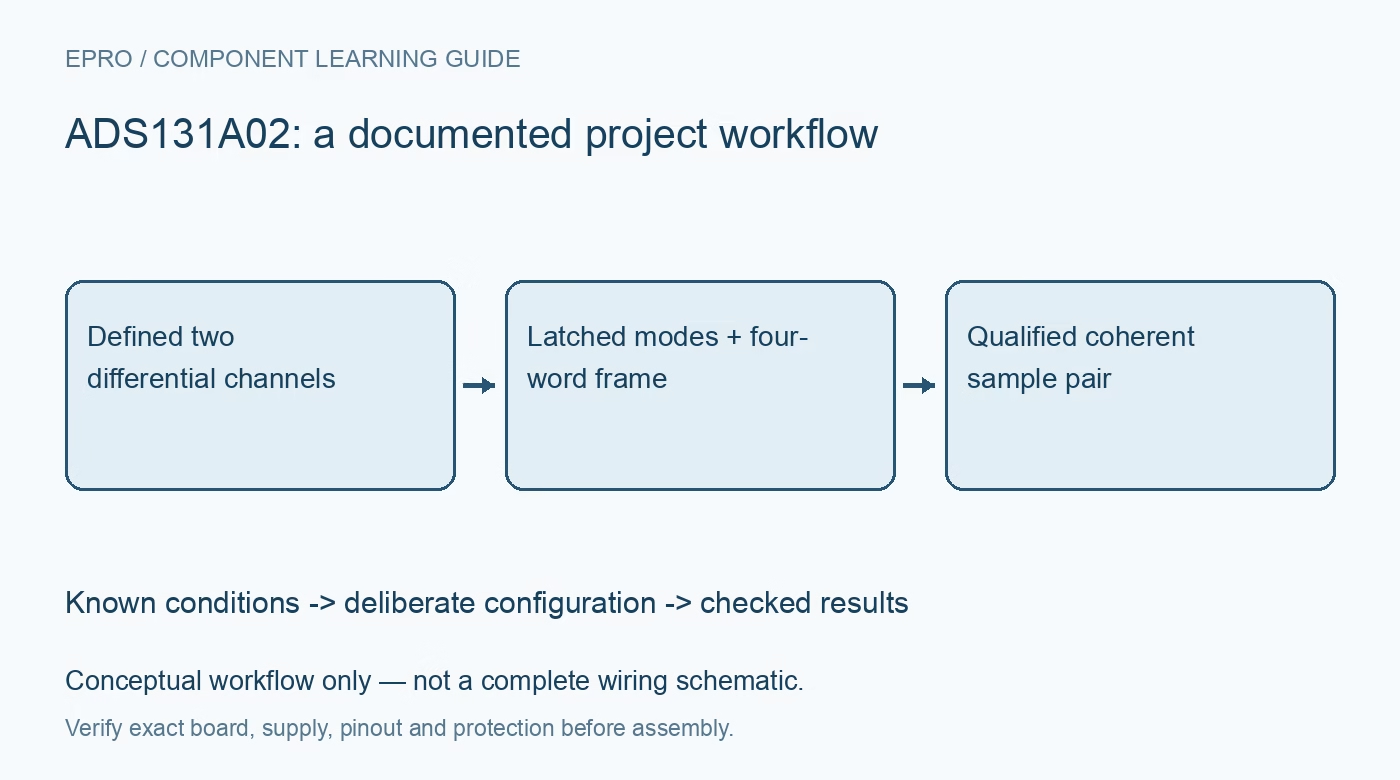
Plan ADS131A02 dual-channel acquisition with latched mode pins, four-word framing, CRC, Hamming checks and valid startup data. This is a documentation-based planning guide, not a report of independent hands-on testing.
1. Define two simultaneous channels and the analog range
ADS131A02 is the two-channel member of a simultaneous-sampling, twenty-four-bit delta-sigma family. Simultaneous sampling supports coherent channel pairs, but it does not remove external sensor delays, amplifier mismatch or filter differences. Establish each differential input and individual pin voltage against the chosen supply and reference configuration. The advertised resolution is not a guarantee of twenty-four noise-free bits or a calibrated power measurement. Record the intended rate and signal bandwidth before selecting the front end. Manufacturer documentation.
2. Choose the documented power configuration
The family supports several analog-supply arrangements, including unipolar operation, bipolar operation and a specifically bounded negative-charge-pump mode. Their voltage conditions are not interchangeable. IOVDD also has its own range and determines the digital interface levels. Follow the corresponding reference and charge-pump requirements instead of assuming every advertised feature is available on one arbitrary supply. Validate input common mode and protection for both channels, particularly if the attached sensors can remain powered during ADC startup. Manufacturer documentation.
3. Read back the mode pins captured at power-up
M0, M1 and M2 determine interface mode, device-word size and Hamming behavior through states captured at power-up. Changing a strap after capture does not simply reconfigure the running interface. Read the hardware-mode status and compare it with the board straps. M1 selects twenty-four-bit, thirty-two-bit or sixteen-bit device words according to its documented state. Distinguish device-word size from conversion resolution and account for the information or padding carried by each transfer. Manufacturer documentation.
4. Use four words in this part’s fixed-frame mode
Normal ADS131A02 fixed-mode acquisition frames use four device words: status, two channel positions and the final CRC position. A six-word frame belongs to the four-channel relative. Dynamic framing instead depends on enabled converters and CRC configuration. Build the parser from the actual device, word size and framing mode. Check complete frame timing and ready indications before decoding samples; a stream with a wrong frame length can still produce plausible-looking values assigned to the wrong record. Manufacturer documentation.
Newest in the store


5. Configure CRC coverage and register writes deliberately
CRC_MODE determines whether validation covers device words or all transmitted and received bits, so implement the exact documented calculation rather than guessing from another ADC. Also note the explicit WREGS exception: the device writes registers before checking that command’s CRC. When prior CRC verification is required, the manufacturer recommends individual WREG operations instead. Read configuration back after changes and confirm the acknowledgement timing. A reported CRC error must not be assumed to mean no configuration changed. Manufacturer documentation.
6. Preserve diagnostics without erasing their meaning
With Hamming enabled, a thirty-two-bit word carries twenty-four conversion bits and eight check bits; a twenty-four-bit word carries only sixteen conversion bits plus eight check bits. Hamming is not a replacement for frame CRC. The ERROR_CNT register counts input integrity errors, saturates at 255 and clears when read. Polling it from multiple tasks can therefore hide events from another logger. Centralize diagnostic reads, retain timestamps and combine the counts with status flags rather than treating a later zero as proof that no errors occurred. Manufacturer documentation.
7. Admit only settled and correctly identified sample pairs
Follow the documented reset, unlock, configuration, converter-enable and startup sequence before accepting measurements. Allow digital-filter settling after relevant changes and preserve overrun or integrity failures as invalid intervals. Apply known bounded inputs to each channel separately to verify sign, scale and identity, then test the intended paired signal. Record clock, reference, mode straps, filter settings and raw frames. This provides traceable acquisition evidence without claiming hands-on accuracy from the theoretical bit count alone. Manufacturer documentation.
Related reading: ADS131A04 Simultaneous ADC: 7 Checks for Startup Straps, Frames and CRC.
Catalog note: The exact-part search did not return a matching Epro listing during preparation. Check the current catalog; this guide makes no price, availability or included-accessory claim.