


LP5569 LED Driver: 7 Checks for Engine Memory and Charge-Pump Setup

LP5569 LED Driver: 7 Checks for Engine Memory and Charge-Pump Setup
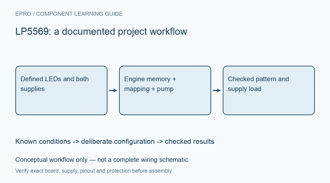
Plan LP5569 effects with separate digital power, charge-pump requirements, valid engine memory, output mapping and current checks. This is a documentation-based planning guide, not a report of independent hands-on testing.
1. Identify nine sinks and both required supply domains
LP5569 provides nine current-sink outputs and three programmable execution engines. VIN operates from 2.5 V to 5.5 V, while V1P8 is a separate digital-power input requiring 1.65 V to 1.95 V. Do not treat V1P8 as a regulator output or connect it directly to the higher VIN rail. Verify the board schematic, grounding and logic-pin limits before powering a module. A familiar I2C interface does not remove the separate digital-supply requirement. Manufacturer documentation.
2. Configure the charge pump for the actual LED network
The adaptive charge pump supports one-times and one-and-a-half-times operation to maintain suitable LED headroom as the source changes. Its flying capacitors, output capacitor and layout are part of that function, not optional decoration. Follow the documented connections for the chosen mode; the unused flying-capacitor pins have specific instructions when the pump is not used. Check output loading and LED voltage limits independently. A charge-pump output is not an unrestricted auxiliary supply for other circuitry. Manufacturer documentation.
3. Separate output current from brightness commands
Each output has individual current control, with a documented maximum of 25.5 mA, and an internal twelve-bit PWM implementation. Check the host register widths rather than assuming internal PWM resolution equals the data width of every command. Choose current according to LED ratings, compliance and total driver dissipation, then use brightness controls for the desired appearance. Start with one low-current output and confirm actual color routing before enabling a full multi-channel pattern. Manufacturer documentation.
4. Allocate usable engine memory rather than the headline total
The programming section specifies 255 usable sixteen-bit instructions at addresses zero through 254; address 255 is reserved. A single engine can allocate at most 128 instructions. Record each engine start address, program counter and allocated range, including any intentional shared routines. Do not assume a headline reference to 256 instructions makes the last location available. Validate compiled lengths and branch targets before upload so one effect does not overwrite another engine’s program or mapping data. Manufacturer documentation.
Newest in the store


5. Load SRAM only in the documented programming state
The engines must be placed in program-load mode before writing SRAM. The interface uses a program-memory page selector followed by page data, so verify page boundaries and byte ordering in the loader. Auto-increment behavior should be explicit in the host configuration. Loading bytes successfully does not establish that an engine is executing the intended start address. Read back supported state and use a short, obvious diagnostic sequence before switching to longer autonomous effects. Manufacturer documentation.
6. Distinguish mapping-pointer updates from active LED ownership
The instruction set contains operations that move a mapping-table pointer and others that actually activate an engine-to-LED mapping. The load-style mapping instructions do not themselves change active ownership. Check which engine, direct register path or master-fader function controls each output at the point of an update. A PWM write that appears ignored may be correct but superseded by another control path. Keep the mapping table and execution state with the saved pattern definition. Manufacturer documentation.
7. Qualify autonomous effects under reset and low battery
Test direct output control first, then one engine, then the intended shared sequence while monitoring both supplies and charge-pump behavior. Check current, temperature, wake behavior and the response to controller reset or an interrupted upload. Record LED routing, current settings, pump configuration, program image and engine start addresses. Fixed optical conditions make visual comparisons more meaningful. This documentation-based guide proposes validation steps; it does not claim that an untested animation or board has passed electrical qualification. Manufacturer documentation.
Related reading: LP55231 LED Driver: 7 Checks for Shared Program Memory and High-Side Outputs.
Catalog note: The exact-part search did not return a matching Epro listing during preparation. Check the current catalog; this guide makes no price, availability or included-accessory claim.