


INA271 Current-Shunt Monitor: 7 Checks for Filtering and Low-Signal Errors

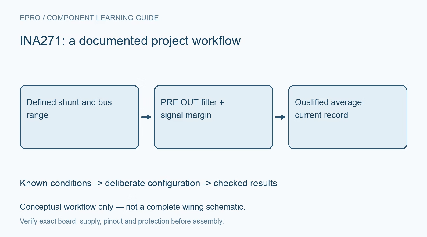
INA271 Current-Shunt Monitor: 7 Checks for Filtering and Low-Signal Errors
Review INA271 fixed gain, PRE OUT filtering, common-mode limits, low-shunt-voltage behavior and meaningful current records. This is a documentation-based planning guide, not a report of independent hands-on testing.
1. Confirm fixed gain and unidirectional operation
INA271 is a voltage-output, unidirectional current-shunt monitor with a fixed overall gain of 20 V/V. The related INA270 uses a different gain, so verify the marking and firmware constant. Negative common-mode capability does not make the measured shunt drop bidirectional. Establish the intended current direction and connect the sense inputs accordingly. A plausible output voltage alone cannot prove the correct gain, shunt polarity or useful operating region has been selected. Manufacturer documentation.
2. Separate the bus common mode from the IC supply
The documented input common-mode range extends from negative 16 V to positive 80 V, while the supply range is positive 2.7 V to 18 V. These are different electrical quantities. Review input differential limits and local-ground relationships independently from the bus voltage. The device provides no galvanic isolation. For initial tests, use a protected low-energy setup rather than treating an extended common-mode rating as permission to connect arbitrary high-voltage systems or ground-referenced test instruments. Manufacturer documentation.
3. Size the shunt for signal margin and dissipation
The ideal output follows the positive shunt voltage multiplied by the fixed gain. Select resistance from the required signal, insertion loss and current-squared-resistance heating, with pulse and temperature limits included. Use Kelvin connections so high-current copper does not become an unintended additional resistor. The datasheet’s operating-region discussion makes shunt signal level especially important for this family. Choosing the smallest possible shunt can reduce heat while moving much of the measurement into a poorly behaved low-signal region. Manufacturer documentation.
4. Do not extrapolate linear accuracy down to zero
The manufacturer separates normal operation at shunt voltages of at least 20 mV from lower-signal cases. Below that level, behavior depends on common-mode voltage relative to ground and the supply. Near zero, output can deviate substantially from a simple gain-times-input calculation; one documented INA271 low-signal case permits an output peak of 0.4 V. That must not be converted blindly into real current. This is more than an ordinary small offset to subtract everywhere. Manufacturer documentation.
Newest in the store


5. Use the PRE OUT and BUF IN filtering provision
The intermediate PRE OUT and BUF IN pins support filtering between the front end and the output buffer. Follow the manufacturer connection and component calculation rather than adding large arbitrary series resistance at the sense inputs. The published example uses filtering to recover average current from a periodic waveform, not to preserve every fast pulse. Confirm the complete filter topology and frequency response. A capacitor value from the example is only appropriate when its averaging objective matches the application. Manufacturer documentation.
6. Budget output range and dynamic limitations
Check upper and lower output swing against supply, load and the receiving ADC. The family bandwidth is condition dependent, and external filtering further changes response and delay. Compare the required average-current update time with filter settling rather than treating a smooth output as instantaneous truth. Include shunt tolerance, temperature drift, gain and operating-region errors in the budget. Typical offset or gain figures on the front page are not guaranteed assembled-system accuracy across all common-mode and low-signal conditions. Manufacturer documentation.
7. Qualify records across the intended operating regions
Apply known positive currents and vary common mode within safe documented limits, explicitly including the smallest current the system intends to report. Compare filtered and unfiltered behavior only through a valid manufacturer-supported configuration. Record supply, bus voltage, shunt value, filter components, sampling interval and temperature. Preserve low-signal or saturated readings as invalid when warranted rather than hiding them with software smoothing. This documentation-based workflow proposes evidence to collect and does not claim independent bench validation or universal precision. Manufacturer documentation.
Related reading: INA280 Current-Sense Amplifier: 7 Checks for Unidirectional High-Side Sensing.
Catalog note: The exact-part search did not return a matching Epro listing during preparation. Check the current catalog; this guide makes no price, availability or included-accessory claim.