


TPS62826 Buck Converter: 7 Checks for 3A Rails and Variant Selection

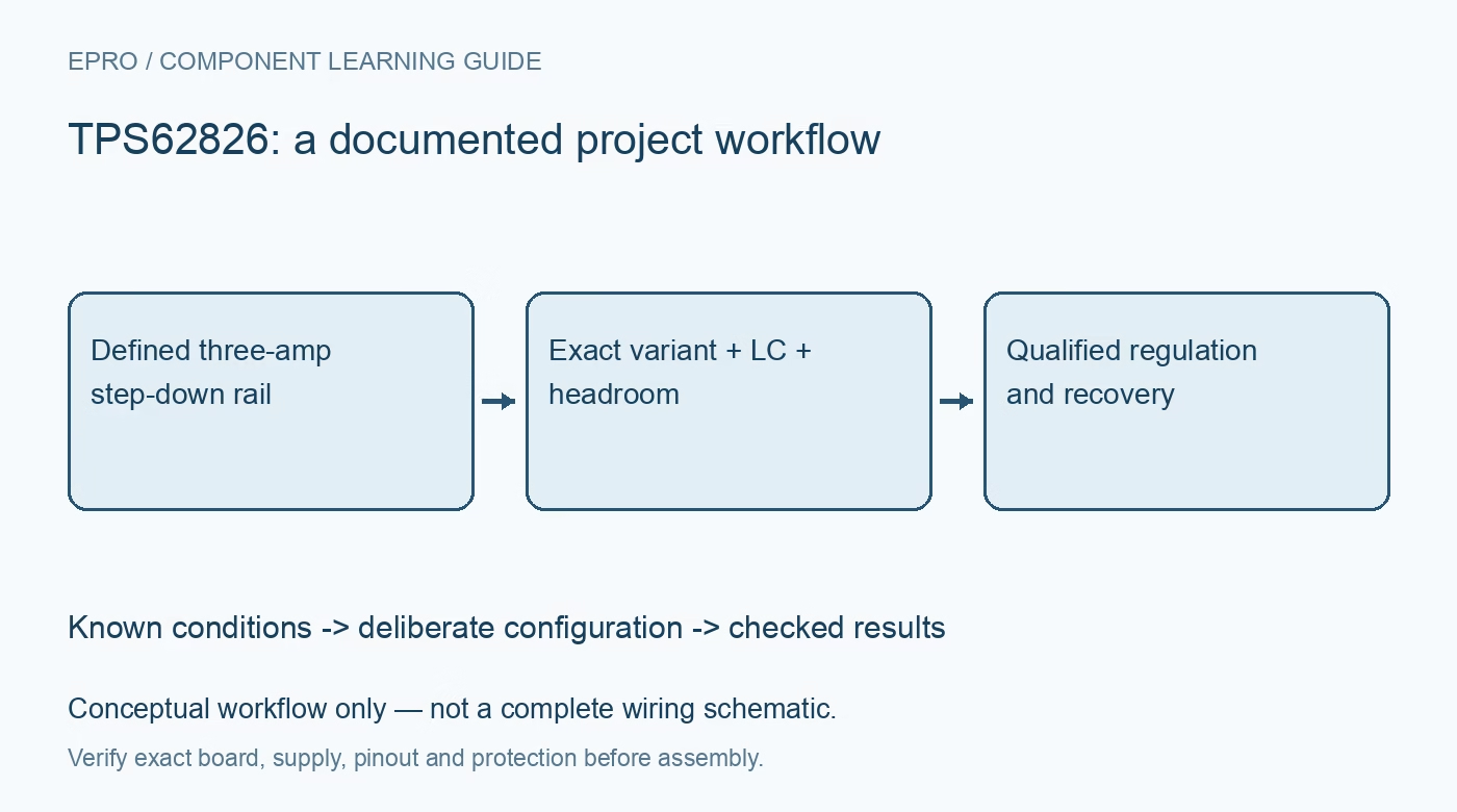
TPS62826 Buck Converter: 7 Checks for 3A Rails and Variant Selection
Review TPS62826 three-amp rail design with PSM versus forced-PWM variants, effective LC values, dropout and thermal checks. This is a documentation-based planning guide, not a report of independent hands-on testing.
1. Read the complete ordering code before assigning behavior
TPS62826 is the three-amp member of a step-down family spanning several current ratings and operating modes. The plain adjustable version uses automatic power-save and PWM operation, while the A variant uses forced PWM. Fixed-output ordering options also exist. Verify the entire code and package rather than treating every similar marking as an adjustable part with identical light-load behavior. The recommended input range is 2.4 V to 5.5 V, not an arbitrary battery or twelve-volt rail. Manufacturer documentation.
2. Define output requirements and the available headroom
The adjustable output range is 0.6 V to 4 V under the documented conditions. Choose the divider using the manufacturer relationship and include resistor tolerance, converter accuracy, ripple and transients in the rail budget. This is a buck converter, so it cannot sustain a programmed output above the available input. Check cable and source resistance at peak load. A three-amp capability label does not establish voltage margin or regulation across the entire discharge curve of an attached source. Manufacturer documentation.
3. Select the inductor and capacitors as a qualified network
Use the recommended effective LC combinations and check inductor saturation current, RMS heating and DC resistance. Include capacitor DC-bias loss and temperature effects rather than assuming nominal microfarads remain available in operation. Keep the input power loop and output filtering consistent with the layout guidance. A lower-resistance inductor can still be unsuitable if its saturation behavior is inadequate. The chosen network affects ripple, transient response and protection behavior together, not just the average DC output. Manufacturer documentation.
4. Match light-load mode to the downstream circuit
The plain device enters power-save behavior as load falls, changing switching activity and ripple characteristics. The forced-PWM relative keeps a different operating pattern and consumption tradeoff. There is no reason to assume a software command can turn one ordering variant into the other. Compare the actual mode against sensitive analog or radio requirements and standby-power goals. The nominal switching-frequency and efficiency headlines retain their operating conditions and should not become universal claims about every assembled rail. Manufacturer documentation.
Newest in the store


5. Account for one-hundred-percent mode near dropout
When input approaches the desired output, the converter can operate with the high-side switch continuously on. The remaining drop depends on switch and inductor resistance and load current. This reduces dropout but does not create boost capability or preserve perfect regulation below the required input. Include trace and connector loss when predicting the minimum usable source voltage. Verify that operating point with the intended load rather than treating a duty-cycle feature as a replacement for a headroom calculation. Manufacturer documentation.
6. Interpret protection and power good as bounded functions
Peak-current limiting, thermal shutdown, hiccup behavior and active output discharge have specific conditions; none provides a precision programmable load-current source. Review EN and the open-drain PG signal against the receiving logic and required sequencing. PG cannot certify low ripple or immunity to fast transients. Check externally powered downstream rails for discharge and backfeed interactions. Do not use protective shutdown as a normal thermal operating point or infer complete power-system safety from the presence of several internal protection blocks. Manufacturer documentation.
7. Validate the actual three-amp implementation
Begin with a current-limited supply and increase load while measuring rail voltage, ripple, inductor temperature and device temperature. Test startup capacitance, light-load behavior, load steps and controlled recovery from overload. Use short, appropriate probe connections to avoid measuring loop pickup as converter noise. Record exact variant, divider, LC parts, ambient conditions and load profile. A family reference layout, emissions example or maximum-current headline does not independently qualify another PCB for regulation, thermal margin or compliance. Manufacturer documentation.
Related reading: TPS62821 Buck Converter: 7 Checks for 1A Limits and Light-Load Behavior.
Catalog note: The exact-part search did not return a matching Epro listing during preparation. Check the current catalog; this guide makes no price, availability or included-accessory claim.