


ADS131M03 ADC: 7 Checks for Coherent Three-Channel Records

ADS131M03 ADC: 7 Checks for Coherent Three-Channel Records
Build ADS131M03 acquisition around five-word SPI frames, CRC behavior, FIFO recovery and validated three-channel timing. This is a documentation-based planning guide, not a report of independent hands-on testing.
1. Plan three simultaneous channels as one acquisition
ADS131M03 is a three-channel simultaneous-sampling converter, not a multiplexed converter that selects one input per sample. Define each differential input, gain and measurement reference before configuring the interface. The supply rails are specified within the documented 2.7 V to 3.6 V range; analog input and common-mode limits require their own checks. Twenty-four-bit output words do not imply twenty-four bits of usable accuracy. Include source noise, reference behavior and gain selection when setting the measurement requirement. Manufacturer documentation.
2. Build the normal frame from five device words
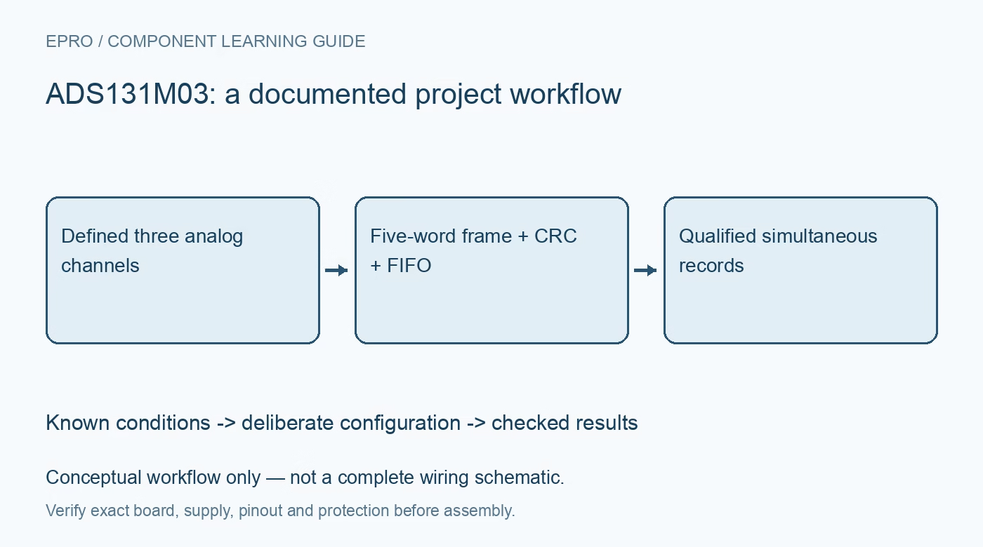
The normal output frame consists of a command response, three conversion words and an output CRC word. That is five words, rather than the six-word layout used by the four-channel relative. Configure the SPI transfer length from the selected word size, which can be sixteen, twenty-four or thirty-two bits, and decode the corresponding padding or sign behavior. Do not let a shared family example silently add a nonexistent fourth channel and shift the CRC position. Manufacturer documentation.
3. Associate responses with the correct command transaction
The response in a frame relates to the preceding command, so an apparently sensible first word is not necessarily an acknowledgment of the command just transmitted. Build the command pipeline explicitly and inspect register readback after configuration. Keep conversion data, command response and communication status as separate fields. When a transfer is interrupted, mark the pipeline uncertain rather than guessing which configuration produced the next values. Reestablish a documented state before attaching new channel labels or calibration metadata. Manufacturer documentation.
4. Do not treat input CRC as a write firewall
The device supports communication checking, but WREG commands execute even when input CRC checking reports a failure. A bad write can therefore change configuration despite a detected communication error. Read back relevant registers and restore a known configuration after a failed transaction. Configure the selected CRC polynomial and initialization correctly; the documented seed is FFFFh. Output CRC is part of the frame structure. Check the received data according to the actual word format rather than validating only the conversion bytes. Manufacturer documentation.
Newest in the store


5. Recover deliberately from the two-deep channel FIFO
Each channel has a two-deep FIFO, which affects what appears after acquisition pauses. Resume with the documented synchronization or prompt two-frame recovery procedure instead of assuming the first returned packet is current. Timestamp the pause and mark the resulting acquisition gap. The recovery choice must fit the host timing and selected rate. A repeated numeric value alone cannot distinguish a quiet input from stale queued data, so keep transfer continuity as an explicit quality condition in the record. Manufacturer documentation.
6. Separate channel simultaneity from filter and phase behavior
Simultaneous converters still require correct interpretation of digital filtering, gain and phase settings. A data-ready edge identifies available results, not a universal zero-latency image of the analog inputs. Use the documented configuration when comparing channels or calculating relative timing. Avoid changing settings midway through an assumed continuous record without a settling policy. Verify the duration requirements on SYNC/RESET because its functions depend on timing. Preserve the actual register set with any data intended for later phase or power analysis. Manufacturer documentation.
7. Validate records before trusting a three-channel application
Use safe known input conditions to check polarity, scaling and channel order, then test communication failure and host pause recovery. Require valid CRC, expected response state and a qualified acquisition epoch before accepting the three values together. A low-voltage evaluation setup does not make a mains-connected measurement system isolated or safe. This documentation-based article reports no independent noise or accuracy results. Keep electrical protection, calibration evidence and packet-quality flags alongside the numerical data rather than relying on resolution alone. Manufacturer documentation.
Related reading: ADS131M04 ADC: 7 Checks for Six-Word Frames and FIFO Recovery.
Catalog note: The exact-part search did not return a matching Epro listing during preparation. Check the current catalog; this guide makes no price, availability or included-accessory claim.