


TPS7A89 Dual LDO: 7 Checks for Two High-Current Quiet Rails

TPS7A89 Dual LDO: 7 Checks for Two High-Current Quiet Rails
Plan TPS7A89 dual 2 A rails with dropout margin, shared package heating, soft-start controls and meaningful power-good checks. This is a documentation-based planning guide, not a report of independent hands-on testing.
1. Treat the two-ampere channels as conditional capabilities
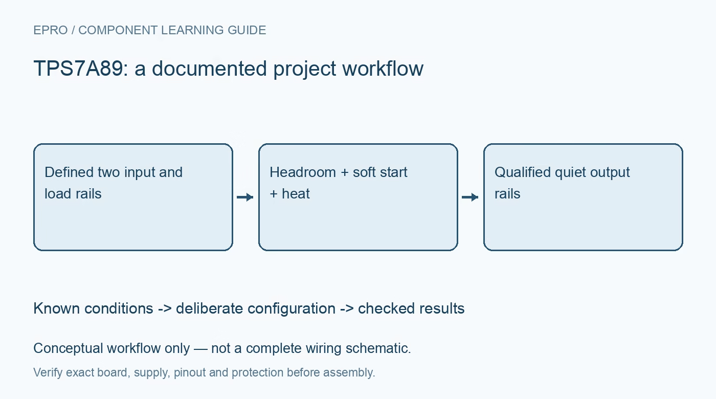
TPS7A89 supplies two independent adjustable LDO outputs, each rated up to two amperes within the documented operating conditions. Its input range is 1.4 V to 6.5 V, and the adjustable output range is 0.8 V to 5.2 V. These ranges do not mean every combination supports the rated current. Define each input, output and load step before selecting the device. The outputs have separate regulation controls but share a package whose thermal capacity must support both channels together. Manufacturer documentation.
2. Establish dropout margin at the actual load
The headline 180 mV dropout at two amperes is a typical specification under stated conditions, not a universal worst-case guarantee. Check the relevant limits over temperature and include source droop, wiring loss and ripple. Once an LDO enters dropout, the output and noise-rejection behavior no longer match a comfortably regulated condition. Evaluate the lowest instantaneous input for each channel, not just a nominal supply label. Leave margin for both sustained load and the current step that matters to the application. Manufacturer documentation.
3. Calculate package heating before emphasizing low noise
For a first conduction estimate, multiply each channel current by its input-to-output voltage difference and add the contributions. Include other dissipation and the actual thermal path through the board. A large voltage drop at two amperes can dominate the design even though the part is described as a quiet regulator. Compare the package and layout guidance against the board copper and ambient conditions. Thermal shutdown is a fault response, not a planned operating method for maintaining a precision rail. Manufacturer documentation.
4. Use effective capacitance and the feedback layout
Follow the recommended input and output capacitor requirements for each channel, including the minimum effective output capacitance rather than only the printed component value. Ceramic capacitance changes with applied voltage, and shared routing can inject load current into the feedback reference. Place the regulation divider and return path according to the layout guidance. Treat optional feed-forward capacitance as part of the documented noise and transient design. Do not assume that adding an arbitrary large capacitor always improves every response. Manufacturer documentation.
Newest in the store


5. Configure SS_CTRL and NR/SS as a coordinated pair
SS_CTRL changes the soft-start charging current: grounding it selects approximately 6.2 microamperes, while connecting it to the corresponding input selects approximately 100 microamperes. The noise-reduction capacitor and this current together affect startup. The documentation warns of overshoot when no noise-reduction capacitor is used with SS_CTRL connected to the input. Follow the specified alternative rather than leaving the control unconsidered. Set and review these connections separately for each output, particularly when the two loads require different startup behavior. Manufacturer documentation.
6. Interpret enables and power-good signals narrowly
Give both enable pins defined states during reset, partial power and shutdown. Read the power-good thresholds, delays and output interface requirements before connecting them to controller logic. A power-good indication qualifies a voltage condition under the device definition; it does not certify low noise, small transient error or acceptable temperature. Likewise, two asserted outputs do not prove the sequencing met a downstream device requirement. Define which events permit the load to begin operating and which fault should stop it. Manufacturer documentation.
7. Qualify the rails with their real load interaction
Check startup with the intended capacitance, followed by independent and simultaneous load changes. Observe whether one channel transition disturbs the other through input impedance, ground routing or shared heating. Measure noise over a stated bandwidth and with a suitable setup before comparing it to a datasheet figure. No such measurements are claimed here. Preserve the chosen divider values, effective capacitors, soft-start connections and thermal conditions so that the final two-rail design is supported by repeatable evidence rather than a family headline. Manufacturer documentation.
Related reading: TPS7A87 Dual LDO: 7 Checks for 500mA Rails and Quiet Sequencing.
Catalog note: The exact-part search did not return a matching Epro listing during preparation. Check the current catalog; this guide makes no price, availability or included-accessory claim.