


TPS7A87 Dual LDO: 7 Checks for 500mA Rails and Quiet Sequencing

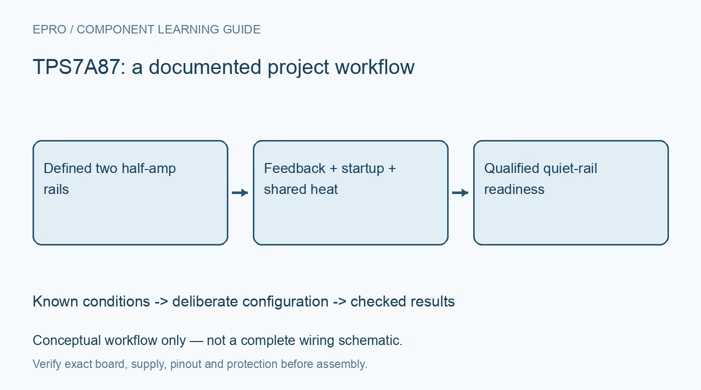
TPS7A87 Dual LDO: 7 Checks for 500mA Rails and Quiet Sequencing
Review TPS7A87 dual 500mA regulation with channel-specific startup, noise capacitors, power-good interpretation and shared thermal limits. This is a documentation-based planning guide, not a report of independent hands-on testing.
1. Use the half-amp rating of this exact device
TPS7A87 integrates two independent LDO channels rated up to 500 mA each under the documented conditions. Do not borrow a one-amp-per-channel claim from a related dual regulator. The input range is 1.4 V to 6.5 V and the adjustable output range is 0.8 V to 5.2 V. Define each load separately, including startup and transient demand. Independent regulation loops still share a package, die temperature and practical board-level coupling paths. Manufacturer documentation.
2. Set both dividers and preserve worst-case headroom
Choose each feedback divider using the documented reference relationship and include resistor tolerance in the output budget. Check dropout at the actual load and temperature rather than applying the headline value to every condition. Upstream ripple, connector loss and simultaneous loading can reduce input margin. Measure at the intended load connection when validating the rail. An ideal divider calculation establishes a target, not the assembled voltage accuracy or behavior during a demanding startup sequence. Manufacturer documentation.
3. Provide effective local output capacitance
Each channel requires the specified capacitor network, with stability documented for a ten-microfarad or larger ceramic output capacitor under the stated conditions. Account for DC-bias loss and temperature instead of relying only on the printed capacitance. Keep sensitive feedback and capacitor returns away from noisy load-current paths. A bulk capacitor on a neighboring rail does not replace local output decoupling. Review input bypassing and feed-forward components as part of the full transient response rather than choosing them independently. Manufacturer documentation.
4. Pair the NR/SS capacitor with its charging mode
Each SS_CTRL input selects the NR/SS charging behavior for its own channel. Ground selects the typical 6.2 microamp mode, while connection to that input rail selects a typical 100 microamp mode. If the NR/SS capacitor is omitted, the corresponding SS_CTRL must be grounded to avoid overshoot. Larger noise-reduction capacitance changes startup timing. Use the relevant limits and tolerances rather than assuming that two channels with nominally equal capacitors will become precision-ready at exactly the same instant. Manufacturer documentation.
Newest in the store


5. Separate the two power-good states from analog readiness
The open-drain PG outputs need compatible pull-ups and a deliberate interpretation. Their documented thresholds indicate a voltage-related status, not measured integrated noise or final precision settling. Decide what happens if only one rail qualifies, and do not combine the signals without preserving the intended fault meaning. For a sensitive ADC or clock circuit, define a separate voltage-error and settling criterion. A PG edge alone cannot substantiate the datasheet microvolt noise headline or release every downstream function safely. Manufacturer documentation.
6. Add both channels to the thermal and coupling budget
Calculate input-to-output drop multiplied by load current for each channel, include regulator consumption and add the heat contributions. A lightly loaded high-drop rail can still warm a precision rail on the same device. Review exposed-pad soldering, copper and ambient conditions before assigning simultaneous continuous ratings. Also consider shared input impedance and downstream signal paths that can back-power a disabled load. Control independence does not eliminate these system-level interactions or establish reverse-current protection. Manufacturer documentation.
7. Measure startup and quiet behavior under representative load
Exercise each channel separately and both together while capturing input, outputs, enables and PG. Check load steps, supply collapse and the selected rail order with bounded initial tests. Noise measurements need an appropriate low-noise setup and declared bandwidth; a general-purpose scope trace is not enough to verify a microvolt specification. Record divider values, capacitors, SS_CTRL states, loads and temperature. This documentation-based guide defines a validation plan rather than claiming that a particular board has already passed it. Manufacturer documentation.
Related reading: TPS7A88 Dual LDO: 7 Checks for Shared Heat and Independent Startup.
Catalog note: The exact-part search did not return a matching Epro listing during preparation. Check the current catalog; this guide makes no price, availability or included-accessory claim.