


TPS22970 Load Switch: 7 Checks for Low-Voltage Power Cycling

TPS22970 Load Switch: 7 Checks for Low-Voltage Power Cycling
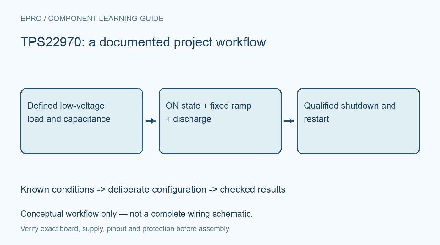
Plan TPS22970 power cycling around its 3.6 V ceiling, internal slew control, unbiased ON pin and 150-ohm output discharge. This is a documentation-based planning guide, not a report of independent hands-on testing.
1. Keep the supply within the low-voltage operating range
TPS22970 is a single-channel load switch intended for input voltages from 0.65 V to 3.6 V. It is not a five-volt rail switch despite sharing a broad product prefix with higher-voltage devices. Include source tolerance and startup overshoot when checking that ceiling. The internal charge pump supports low-resistance switching at low input voltage, but it does not regulate the output to a different voltage. Define the rail and required load current before choosing the switch for a power-cycle function. Manufacturer documentation.
2. Provide a defined ON signal without assuming a pull resistor
The active-high ON input is compatible with low-voltage control signals under the documented conditions. It has no internal bias and must not float. Choose an external default that keeps the downstream load in a deliberate state while the processor resets or its GPIO is unconfigured. Check the control voltage limits independently from VIN, including a controller that remains powered after the switched supply collapses. A firmware command cannot establish a safe power-up state before the firmware has begun running. Manufacturer documentation.
3. Distinguish turn-on time from output rise time
The device uses internally controlled slew rather than an external timing capacitor. The documented turn-on delay and output rise interval are different quantities, and both depend on their specified conditions. Do not use a headline turn-on time as the capacitor charging slope in an inrush calculation. Estimate charging current from the actual voltage rise and output capacitance, add the load current during startup, and check source droop. An internally shaped ramp reduces inrush but is not a precision programmable startup timer. Manufacturer documentation.
4. Treat current capability and resistance as conditional
The advertised four-ampere switch capability must be evaluated with the package, board and operating conditions. Typical on-resistance changes with input voltage, so the smallest quoted value does not describe every low-voltage rail. Estimate drop and conduction heating with suitable margins, including the total load and connector resistance. The eight-ball wafer-level package needs appropriate fabrication and assembly. A favorable device resistance figure does not mean an improvised adapter or narrow PCB trace can sustain the same current without excessive heating. Manufacturer documentation.
Newest in the store


5. Include the output discharge path in power sharing
When disabled, the switch connects a quick-discharge path between VOUT and ground, with a typical resistance of 150 ohms that varies with conditions. This helps remove stored output charge but can also load an output maintained by another source. Review back-power through signal cables and peripheral interfaces before assuming the load is truly unpowered. ON low does not create a generic isolated port. Calculate the discharge behavior using the actual capacitance and downstream paths rather than treating shutdown as an instantaneous zero-volt event. Manufacturer documentation.
6. Keep thermal shutdown outside normal operation
Thermal shutdown turns the switch off when the junction becomes too hot and allows recovery after cooling. That response is protection, not a substitute for normal current and temperature design. Do not treat this part as a programmable current limiter merely because it has a protective shutdown function. Evaluate a downstream short through the upstream source and any dedicated protection. Repeated automatic thermal cycling can create unexpected load restarts, so define what the system should do after the first detected power fault. Manufacturer documentation.
7. Verify complete power removal before accepting a restart
Test startup and shutdown with representative capacitance and the actual external signal connections. Observe the load voltage long enough to see discharge, then try the shortest intended off interval and confirm a genuine peripheral reset. Repeat with a weak input source and realistic steady load while checking temperature. No independent timing or thermal measurements are claimed here. Preserve the ON default, source conditions and accepted minimum off interval so a later firmware change does not silently invalidate the power-cycle behavior. Manufacturer documentation.
Related reading: TPS22969 Load Switch: 7 Checks for Fixed Slew and High-Current Rails.
Catalog note: The exact-part search did not return a matching Epro listing during preparation. Check the current catalog; this guide makes no price, availability or included-accessory claim.