


TPS22969 Load Switch: 7 Checks for Fixed Slew and High-Current Rails

TPS22969 Load Switch: 7 Checks for Fixed Slew and High-Current Rails
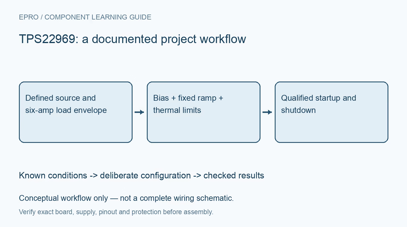
Plan TPS22969 rail control with valid bias, fixed startup timing, inrush estimates, reverse paths, discharge and thermal checks. This is a documentation-based planning guide, not a report of independent hands-on testing.
1. Identify a biased switch with fixed startup behavior
TPS22969 is a single-channel N-channel load switch with separate VIN and VBIAS connections. It supports up to 6 A continuous switch current under appropriate conditions and uses an internally controlled fixed slew rate. Unlike some related switches, it does not provide an external CT adjustment pin. Trace the repeated power pins, ON and exposed thermal pad against the package drawing. A board designed for a configurable-ramp part is not automatically a drop-in match. Manufacturer documentation.
2. Keep VIN at or below the qualified bias condition
The documented ranges are 0.8 V to 5.5 V for VIN and 2.5 V to 5.5 V for VBIAS. For the specified resistance performance, maintain VIN no greater than VBIAS. The manufacturer states that operation with VIN above VBIAS may still occur but performance is not guaranteed there. Do not promote that observation into a recommended operating point. Review supply order and local bypassing before connecting a low-voltage high-current rail controlled by a separate bias source. Manufacturer documentation.
3. Define ON through boot and brownout
ON is active high and must not float. Check the guaranteed input thresholds against the controlling logic and provide an intentional off state while the host is resetting. A valid control voltage does not power the internal driver if VBIAS is absent. Include sequencing of VIN, VBIAS and downstream interfaces when reviewing possible back-power paths. The firmware command state and the actual load voltage should be observed separately during abnormal supply transitions and cable insertion. Manufacturer documentation.
4. Estimate inrush from the documented ramp conditions
Fixed slew does not mean one identical rise time at every input, bias and load condition. The published example rise time is associated with specific VIN and VBIAS values, and the characteristic plots show their influence. Estimate capacitive inrush from capacitance multiplied by output slew rate, then include active load current. Verify the upstream rail dip on the assembled board. Controlled turnon is not a precision current limit and cannot guarantee startup into an arbitrary short or constant-power load. Manufacturer documentation.
Newest in the store


5. Calculate resistance loss and package heating
The headline 4.4 milliohm on-resistance belongs to stated low-input-voltage and five-volt-bias conditions. Use the applicable electrical limits and temperature behavior when calculating voltage drop and current-squared-resistance loss. Check PCB copper, pad soldering, connector and trace losses together with the device. Six amperes through a small package requires a defensible thermal implementation. A cool short pulse or an unloaded output measurement cannot establish continuous operation at the maximum advertised current. Manufacturer documentation.
6. Evaluate discharge and reverse current during collapse
The integrated quick-output-discharge function helps bring the output down when disabled, but it can also load an externally powered downstream rail. The body diode in the N-channel switch matters if VOUT exceeds VIN as the source collapses. Review input and output capacitance, external supply paths and the manufacturer recommendations rather than assuming off means bidirectional isolation. The suggested capacitance ratio is application guidance for controlling rail dip and backflow, not a universal replacement for power-sequence analysis. Manufacturer documentation.
7. Verify loaded startup and every relevant supply order
Capture VIN, VBIAS, ON, VOUT and source current during a bounded startup test, then repeat with representative capacitance and load. Inspect turnoff discharge, source removal and any condition where the output can remain powered elsewhere. Use current limiting for initial work and stop if temperature or rail excursions exceed the planned envelope. Record layout, capacitance, load profile and observations. This documentation-based review defines evidence to collect, not a claim that an untested rail already meets its requirements. Manufacturer documentation.
Related reading: TPS22968 Dual Load Switch: 7 Checks for Shared Bias and Rail Sequencing.
Catalog note: The exact-part search did not return a matching Epro listing during preparation. Check the current catalog; this guide makes no price, availability or included-accessory claim.