


THVD1550 RS-485 Transceiver: 7 Checks for 50Mbps Timing and Loading

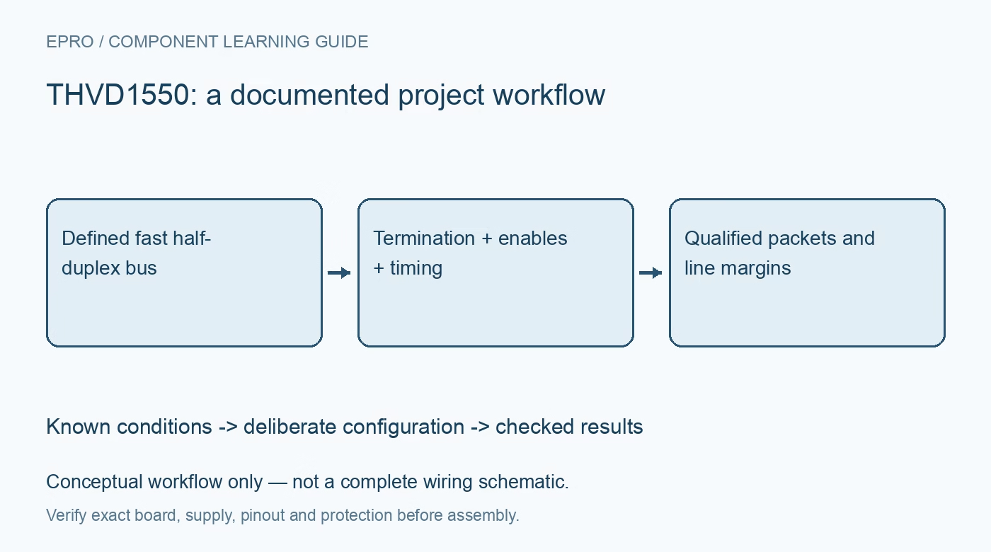
THVD1550 RS-485 Transceiver: 7 Checks for 50Mbps Timing and Loading
Review THVD1550 half-duplex 50Mbps links with correct 5V interfaces, node loading, turnaround, common mode and protection limits. This is a documentation-based planning guide, not a report of independent hands-on testing.
1. Select the fast half-duplex device deliberately
THVD1550 is the half-duplex member rated for signaling up to 50 Mbps in this family. It has driver and receiver enables; other relatives differ in speed, duplex arrangement and controls. Verify the exact device and pinout before applying a shared family schematic. The component handles differential electrical signaling, not packet scheduling or error correction. A UART or other controller, application protocol and appropriately designed cable network are still required for a functional communication system. Manufacturer documentation.
2. Check both directions of the five-volt logic interface
The supply requirement is 4.5 V to 5.5 V. Evaluate controller-to-transceiver input thresholds separately from receiver-output compatibility with the controller. A 3.3 V output meeting an input threshold does not prove that a 3.3 V input can tolerate the transceiver R voltage. Include level-translation delays in the timing budget if needed. Defined enable states during reset and powered-off behavior matter as much as normal static logic levels when the host and transceiver start at different times. Manufacturer documentation.
3. Do not borrow the slower family member’s node count
The manufacturer comparison table associates the fast half-duplex variant with a maximum of 196 receiver loads under its loading model, rather than the 256-node figure shown for slower variants. Neither number guarantees a practical network of that size at maximum signaling rate. Termination, stubs, connectors, cable capacitance and topology impose additional constraints. Calculate the actual DC load and evaluate signal integrity. A family headline cannot replace the exact part’s receiver-loading specification or system-level validation. Manufacturer documentation.
4. Budget enable and turnaround against the bit interval
DE high enables transmission and active-low RE low enables reception. Choose whether reception remains active while sending and handle local echo deliberately. Release DE only after the final physical bit has completed, including relevant device timing. At 50 Mbps, small delays and skew consume a substantial fraction of a bit interval. Use guaranteed timing limits and controller behavior rather than typical propagation delay alone. An empty software queue is not proof that the line has finished transmitting. Manufacturer documentation.
Newest in the store


5. Validate termination and topology for fast edges
Use cable-compatible termination at the intended physical ends and control stub length and connector discontinuities. A low average traffic rate does not necessarily eliminate reflections caused by fast transitions. Inspect differential waveforms and common-mode behavior with representative nodes attached. Avoid assuming a star layout or an arbitrary cable length is supported by the data-rate headline. Include any bias network and external protection capacitance in the analysis because those components alter driver loading and the received waveform. Manufacturer documentation.
6. Separate operating common mode from protection claims
The family specifies an extended operational common-mode range of plus-and-minus 15 V under the documented conditions. Absolute limits, ESD tests and fast-transient tests describe different stress categories. The transceiver is not galvanically isolated, and the protection ratings do not establish immunity to sustained overvoltage, every surge waveform or incorrect grounding. Review the actual installation exposure. Failsafe receiver logic defines an absent-signal state but cannot certify cable continuity, correct addressing or a healthy remote device. Manufacturer documentation.
7. Qualify packet integrity with timing evidence
Start with two nodes, a known cable and a conservative traffic rate, then progress toward the intended operating conditions. Capture DE, host data and bus waveforms while tracking framing and application-level integrity errors. Test reset, loss of one node’s supply and controlled cable reconnection. Record topology, termination, supply, cable and controller settings. A single valid packet or a clean repetitive pattern does not establish long-term reliability, maximum distance or compliance for an untested deployment. Manufacturer documentation.
Related reading: THVD1520 RS-485 Transceiver: 7 Checks for 10Mbps Bus Integrity.
Catalog note: The exact-part search did not return a matching Epro listing during preparation. Check the current catalog; this guide makes no price, availability or included-accessory claim.