


TMUX1108 Precision Multiplexer: 7 Checks for Bipolar Signals and Settling

TMUX1108 Precision Multiplexer: 7 Checks for Bipolar Signals and Settling
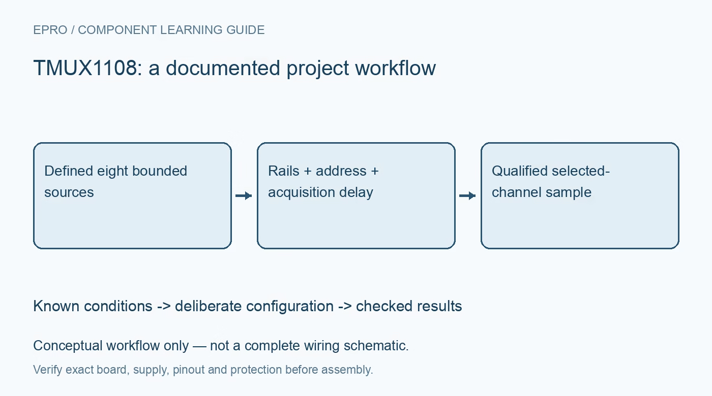
Plan TMUX1108 eight-channel acquisition with valid dual rails, enable logic, channel addressing, leakage and settled measurements. This is a documentation-based planning guide, not a report of independent hands-on testing.
1. Recognize one selected path rather than eight independent switches
TMUX1108 is an eight-to-one analog multiplexer with eight source terminals and a common drain. A three-bit address selects the connected source when the device is enabled. Although the signal path is bidirectional, the wiring still determines which sources can contend or remain externally connected. Map every physical input to its address before starting acquisition. Do not reuse the control model of a four-channel SPST switch or assume each channel has a separate enable pin. Manufacturer documentation.
2. Bound bipolar signals by the actual supply rails
The device supports single-supply operation and documented dual-supply configurations, including nominal plus-and-minus-2.5 V operation. The source and drain voltages must remain between VSS and VDD, and the total rail span must satisfy its own limit. Negative analog capability does not permit arbitrary negative voltages or excessive supply separation. Check power sequencing when a sensor can stay powered after the multiplexer. Fail-safe digital logic is a different feature from unrestricted powered-off analog protection. Manufacturer documentation.
3. Implement the active-high enable and address table
EN low opens all channels regardless of the address. EN high connects S1 for address 000 through S8 for address 111. Define all address and enable levels during boot and reset, and keep the digital controls within their documented ground-referenced range even when VSS is negative. A useful initialization test assigns a different known bounded voltage to each input and verifies the observed order. This distinguishes wiring errors from later scaling or software indexing mistakes. Manufacturer documentation.
4. Budget on-resistance with the source and receiver
The low on-resistance headline is characterized under specified supply, signal and temperature conditions. Include its appropriate limit and variation with the complete source resistance and ADC input network. A high-impedance meter can hide a loading error that appears when a switched-capacitor ADC begins acquiring. Evaluate signal attenuation and settling separately. If the selected source needs buffering, compare the buffer input range, output drive and stability against the same operating envelope rather than choosing by bandwidth alone. Manufacturer documentation.
Newest in the store


5. Evaluate leakage and unselected-channel coupling
Leakage can create significant error with high-impedance sources, especially at elevated temperature. Consider both selected-path behavior and off-state leakage from the other inputs, including board contamination and connector leakage. Off-state capacitance can also couple a fast unselected signal into the measured node. An open channel is therefore not an ideal isolation barrier. Use realistic neighboring waveforms during validation instead of grounding every unused input and assuming the same error will apply in the final system. Manufacturer documentation.
6. Allow settling after break-before-make transitions
Break-before-make switching prevents the normal selected paths from overlapping during a change, but it does not guarantee that the new input is immediately accurate. Charge injection, source impedance and receiver capacitance determine the transient after selection. Choose an acquisition delay from the actual error requirement and verify it with worst-case channel steps. The first ADC sample may need to be discarded or delayed. A fast digital address transition is not the same thing as a settled analog measurement. Manufacturer documentation.
7. Preserve channel identity with each accepted sample
Capture channel address, enable state, timestamp and relevant configuration with the data record. Test the largest intended positive-to-negative transitions while keeping every pin inside its limits. Include supply ramps and controller reset, and verify all-off behavior with the real receiver attached. Record source impedance, filter values, acquisition delay and temperature. These checks support a particular multiplexed measurement system without claiming that every channel achieves the headline precision or that this conceptual workflow is a complete wiring schematic. Manufacturer documentation.
Related reading: TMUX1119 Precision Switch: 7 Checks for Leakage, Charge Injection and Settling.
Catalog note: The exact-part search did not return a matching Epro listing during preparation. Check the current catalog; this guide makes no price, availability or included-accessory claim.