


TPS7A4001 Regulator: 7 Checks Beyond Its 100 V Input Rating

TPS7A4001 Regulator: 7 Checks Beyond Its 100 V Input Rating
Plan TPS7A4001 auxiliary rails around thermal loss, feedback limits, capacitor ratings, enable sequencing and high-voltage safety boundaries. This is a documentation-based planning guide, not a report of independent hands-on testing.
1. Treat voltage tolerance and useful output power separately
TPS7A4001 supports a documented input operating range from seven to one hundred volts and an output-current capability up to fifty milliamperes. Those two headlines do not mean the maximum current is thermally practical at the largest input-output difference. Define the actual auxiliary load, source range and board environment first. This device is a nonisolated linear regulator, not a complete mains power supply. Its rating does not remove hazardous-voltage handling, isolation, enclosure or system protection requirements. Manufacturer documentation.
2. Calculate dissipation before choosing a large voltage drop
A first load-dependent heat estimate is input-output voltage difference multiplied by load current, with additional device consumption considered as appropriate. Even a modest auxiliary current can create substantial loss when the voltage difference is large. Compare the result with the package, copper and ambient thermal design rather than assuming the current limit establishes a usable continuous operating point. If the thermal budget fails, choose a suitable architecture instead of relying on repetitive shutdown to make an oversized linear voltage drop appear acceptable. Manufacturer documentation.
3. Keep feedback near its intended low-voltage operating level
The output is adjustable through the external feedback divider, but the FB terminal has much lower voltage limits than the high-voltage input and output terminals. Follow the reference relationship, divider-current requirement and resistor-rating guidance from the documentation. Include divider tolerance and leakage in the output error budget. Never apply a high output directly to FB on the assumption that all pins share the input rating. Verify the fitted divider and intended output using a safely limited setup before connecting sensitive electronics. Manufacturer documentation.
4. Rate capacitors for voltage as well as capacitance
The manufacturer calls for at least the specified input and output capacitance under relevant tolerance and temperature conditions, including approximately one microfarad input and 4.7 microfarads output guidance. Check effective capacitance and adequate voltage rating for the actual node and expected transients. Component size alone is not evidence of sufficient rating. Place bypassing and the output return as directed. High-voltage clearance, discharge and stored-energy controls remain system responsibilities; a compact regulator footprint does not imply that a compact exposed prototype is safe. Manufacturer documentation.
Newest in the store


5. Review enable and reverse-voltage conditions
The enable terminal supports logic-level operation, and the documented connection rules include keeping its voltage no greater than VIN. Check startup, shutdown and any controller that remains powered after the input rail falls. Also review conditions where output capacitance or another source could hold OUT above a collapsing IN. Do not assume internal current limiting provides every reverse-power protection function. Establish allowed pin relationships throughout sequencing, using the exact operating and stress specifications rather than only the normal-state schematic labels. Manufacturer documentation.
6. Use package protection as a last line of defense
The PowerPAD connection and board thermal path are central to removing heat. Follow the ground and pad guidance and assess the real steady-state temperature. Current limit and thermal shutdown help manage faults, but they do not certify continuous operation or protect every surrounding component. Define the system response to an overtemperature event and any automatic restart. High-voltage construction and energized measurements should be performed only with suitable expertise, rated equipment and a protected setup; this conceptual guide is not a wiring plan for exposed hazardous circuits. Manufacturer documentation.
7. Qualify the auxiliary rail within a controlled envelope
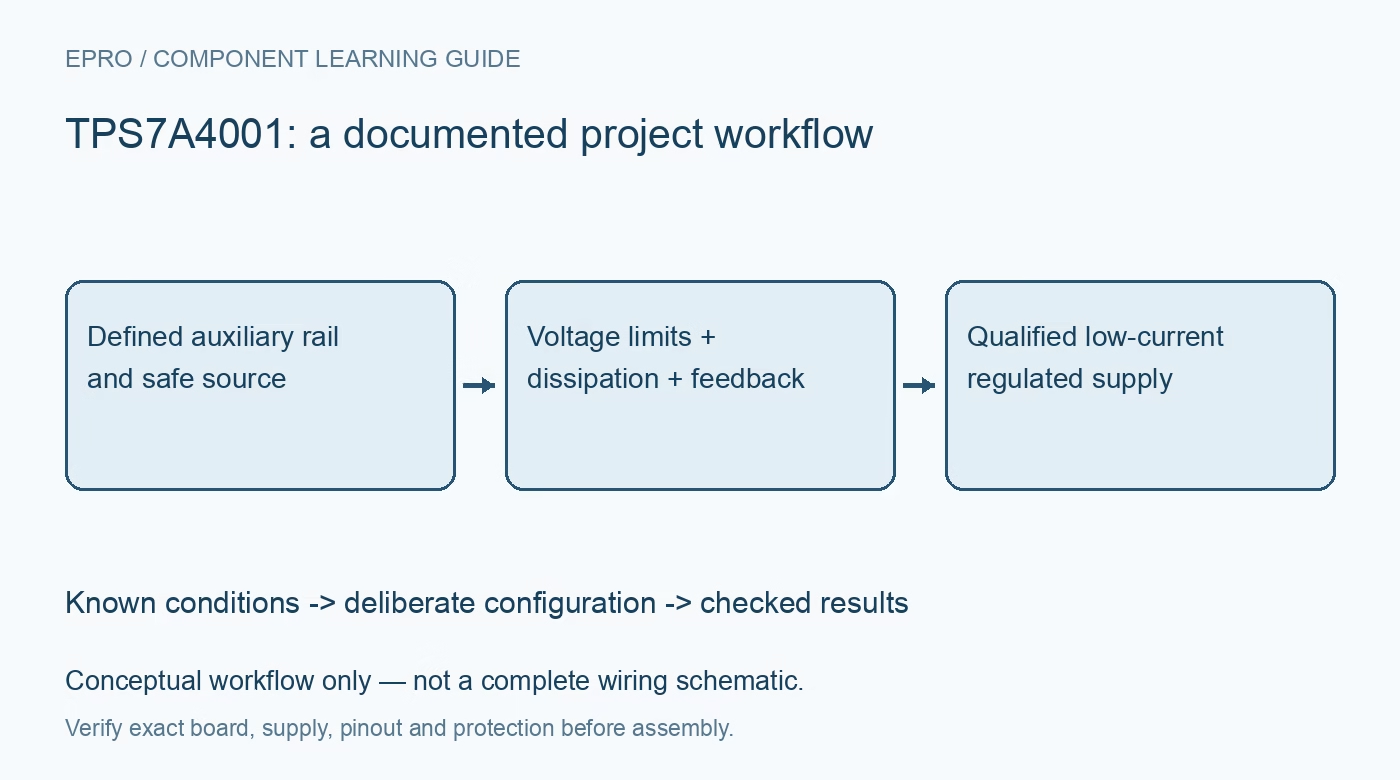
Begin with a safe limited source arrangement appropriate to the project, verifying the divider setting and load behavior before extending operation within the approved system limits. Check startup, load changes and sustained temperature with rated measurement equipment and protection. Record input range, actual current and thermal conditions. No independent high-voltage, fault-survival or accuracy results are claimed here. Keep evidence for regulation separate from evidence for electrical safety so a stable output is never mistaken for proof that the entire installation is safe. Manufacturer documentation.
Related reading: TPS7A84 LDO: 7 Checks for a Quiet Three-Ampere Rail.
Catalog note: The exact-part search did not return a matching Epro listing during preparation. Check the current catalog; this guide makes no price, availability or included-accessory claim.