


TPS62866 Buck Converter: 7 Checks for a Reset-Safe 6 A Core Rail

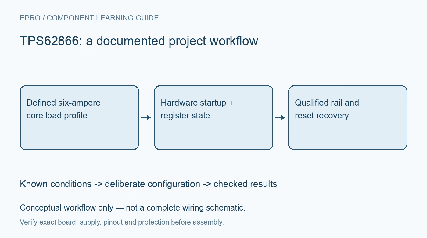
TPS62866 Buck Converter: 7 Checks for a Reset-Safe 6 A Core Rail
Qualify TPS62866 core rails with six-ampere power-stage planning, hardware startup selection, exact VID or PG behavior and reset-aware firmware. This is a documentation-based planning guide, not a report of independent hands-on testing.
1. Match the six-ampere part to the real core load
TPS62866 is the six-ampere member of its programmable converter family. That capability depends on the specified electrical, thermal and layout conditions, not simply the nominal current printed in a product description. Establish sustained, startup and transient core demand together with the upstream source impedance. Review the small wafer-level package and high-current paths early. A processor can create a difficult fast load step even when its long-term average current looks modest, so the qualification must cover the actual performance states. Manufacturer documentation.
2. Choose the exact VID or power-good option
The full orderable code determines whether the shared startup-selection terminal becomes VID or a power-good indication afterward. These functions are not simultaneously present on every option. Confirm the device before routing a processor output or status input to that pin. The PG option has its own described electrical behavior, including a low indication when regulated, and disables the second output-voltage register. Do not treat it as a conventional interchangeable open-drain pin based on a different regulator family. Manufacturer documentation.
3. Protect the hardware-selected startup state
An external VSET resistor determines the initial voltage and I2C address during the enable delay. Check the specified value, tolerance and connected circuitry during that measurement interval. Extra current paths or excessive capacitance can corrupt the resistor interpretation. The load must tolerate the hardware-selected startup voltage before software can intervene. Document that initial condition separately from a later operating setpoint so a firmware correction is never presented as protection against a voltage that may already have been applied during boot. Manufacturer documentation.
4. Make every voltage transition a coordinated load event
For a VID version, the pin selects between two programmed voltage registers after startup. Set both values intentionally and obey the load requirements for changing clock frequency, reset or operating mode. Choose the converter ramp and switching-mode policy deliberately rather than assuming every allowed register write is safe for the processor. The output-code table includes values with wider accuracy concerns, so use its exceptions as well as its nominal step size. Read back the configuration before permitting a performance-state transition. Manufacturer documentation.
Newest in the store


5. Design the power stage for transient and thermal margin
Select inductor, effective input and output capacitance and current ratings from the manufacturer guidance. Include saturation, ripple current, capacitor bias reduction and the thermal path through the board. Locate switching loops and output sensing as specified; remote source droop or poorly placed sensing can invalidate a nominal setpoint. Forced PWM and automatic power-save operation also produce different efficiency and waveform behavior. Qualify the selected mode with the load rather than interpreting the nominal switching frequency as a constant at every operating point. Manufacturer documentation.
6. Treat reset as loss of the previous register contract
Input brownout, EN going low and the documented control reset can restore defaults and start a new hardware-selection sequence. Firmware must not assume that previously programmed voltages, mode or ramp choices survive those events. Define a recovery policy that reestablishes the intended register image and load permissions. A successful bus acknowledgment is only communication evidence, not proof that voltage scaling completed or that the core is safe to run at its previous clock. Preserve configuration epochs in diagnostic logs. Manufacturer documentation.
7. Qualify boot, scaling and recovery under representative load
With appropriate current limiting and protection, inspect hardware startup, address recognition, intended voltage states and a deliberately controlled restart. Check the highest intended sustained load and demanding transitions at relevant source and temperature conditions. Use suitable measurement connections for ripple and transient evaluation. This article claims no independently measured efficiency or rail performance. Keep the exact option, VSET resistor, register image and accepted load sequence together so a board or firmware revision cannot silently inherit a qualification that no longer applies. Manufacturer documentation.
Related reading: TPS62864 Buck Converter: 7 Checks for I2C Voltage Scaling.
Catalog note: The exact-part search did not return a matching Epro listing during preparation. Check the current catalog; this guide makes no price, availability or included-accessory claim.