


TPS62864 Buck Converter: 7 Checks for I2C Voltage Scaling

TPS62864 Buck Converter: 7 Checks for I2C Voltage Scaling
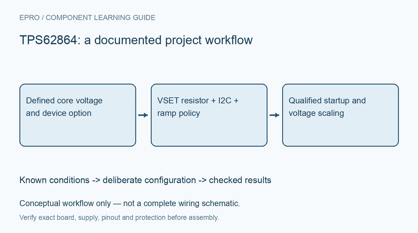
Plan TPS62864 four-ampere core rails with resistor-selected startup, exact VID or PG options, register reset behavior and safe voltage changes. This is a documentation-based planning guide, not a report of independent hands-on testing.
1. Select the four-ampere device and exact pin option
TPS62864 is the four-ampere member of a family that also includes a six-ampere device. Its ordering options assign the shared startup-selection terminal to either VID or power-good behavior after startup. Those functions are not simultaneously available on every version. Confirm the full orderable part before routing a processor control or status signal to that terminal. Check the fifteen-ball wafer-level package and its assembly requirements rather than transferring a larger converter footprint based only on a similar family name. Manufacturer documentation.
2. Program startup voltage and address with the VSET resistor
During the enable delay, the device reads an external resistor to determine both startup voltage and I2C slave address. Use the specified resistor table and accuracy rather than choosing a voltage value independently from the address. Additional current paths or excessive capacitance on that terminal can cause an incorrect startup selection. Review connected controller pins and measurement fixtures during this interval. A software correction after boot cannot protect a sensitive core from an unacceptable voltage that was already applied before communication became available. Manufacturer documentation.
3. Distinguish hardware startup from software voltage range
The resistor-selected startup options differ from the full programmable output-register range. The registers provide five-millivolt steps over the documented range, with specific codes discouraged because their accuracy can have wider tolerance. Respect those exceptions rather than assuming every numerically valid byte is equally suitable. Wait for the documented interface-ready point before programming. Keep the intended initial rail and subsequent application setpoint in a configuration record, and verify which one the load actually sees during a reset or interrupted startup. Manufacturer documentation.
4. Use VID only on the option that implements it
After startup, the VID option selects between two programmed output-voltage registers. Define both values and the permitted transition before allowing a processor or controller to toggle the pin. The PG option instead has different behavior and disables the second output register. Do not treat that status terminal as a conventional interchangeable open-drain signal without reading its described drive and resistor arrangement. On the PG option, the documented regulated indication is low, which must be interpreted correctly by downstream logic. Manufacturer documentation.
Newest in the store


5. Coordinate voltage ramps and switching mode with the load
The control register selects operating features including forced PWM or power-save behavior, voltage-change ramp speed and related transition behavior. A legal converter voltage change is not necessarily a legal processor operating sequence. Coordinate clock frequency, reset and load requirements with the rail transition. Forced PWM can reduce light-load ripple at an efficiency cost, while automatic power-save mode changes the waveform. Qualify the actual selected mode instead of claiming a fixed switching pattern at every load from the nominal frequency headline. Manufacturer documentation.
6. Reapply configuration after documented reset events
Register contents can reset when input falls below the specified condition, EN transitions low or the control reset command is used. Those events can restore hardware-selected startup behavior. Design firmware to detect or deliberately manage a new configuration epoch instead of assuming the previous voltage settings persist indefinitely. Include source brownout and a failed communication sequence in the recovery policy. Read back the intended settings before releasing a sensitive load, and avoid reporting a successful I2C acknowledgment as proof that the whole rail sequence completed safely. Manufacturer documentation.
7. Qualify the power stage and scaling sequence together
Select the inductor, effective capacitors and layout from the manufacturer guidance, then check the actual current profile and thermal conditions. With a current-limited source, verify resistor-selected startup, address recognition, both intended voltage states and recovery after reset. Observe the rail through transitions under representative load. No independent efficiency, ripple or scaling-time results are claimed here. Keep the exact option, VSET resistance, register image and load permissions together so software updates cannot silently change the accepted power behavior. Manufacturer documentation.
Related reading: TPS62822 Buck Converter: 7 Checks for a Two-Ampere Load Profile.
Catalog note: The exact-part search did not return a matching Epro listing during preparation. Check the current catalog; this guide makes no price, availability or included-accessory claim.