


TPS62822 Buck Converter: 7 Checks for a Two-Ampere Load Profile

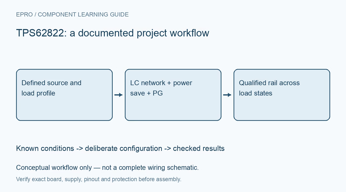
TPS62822 Buck Converter: 7 Checks for a Two-Ampere Load Profile
Qualify TPS62822 two-ampere rails through exact family selection, effective LC values, power-save behavior and realistic transient loading. This is a documentation-based planning guide, not a report of independent hands-on testing.
1. Confirm the two-ampere family member and footprint
TPS62822 is the two-ampere device in a family that also includes one- and three-ampere versions. The family front page includes some resistance and current statements specifically identified with the three-ampere member, so do not transfer them unqualified to this part. Confirm the exact orderable device and eight-pin package before borrowing a related layout. A shared family description is useful for orientation, but the device comparison table and applicable electrical limits determine the actual converter being installed. Manufacturer documentation.
2. Write a load profile rather than one average current
List sleep, active, startup and short-duration demand for the powered circuit. A peripheral that averages little current can still impose a large transient when its radio, processor or output stage wakes. Compare that profile with the converter capability, input source and output storage. Keep normal load design separate from cycle-by-cycle limiting, hiccup protection and thermal shutdown. Those protective behaviors help manage faults; they are not intended as ordinary operating points for a load that exceeds the selected two-ampere device. Manufacturer documentation.
3. Check the full input range and high-duty endpoint
The input operates from 2.4 V to 5.5 V, with adjustable output from 0.6 V to 4 V under the documented conditions. Allow for source impedance, connector drop and a depleted battery before evaluating the minimum input. Hundred-percent duty-cycle operation reduces dropout but cannot boost a source below the required output or eliminate conduction loss. Determine the acceptable output at the worst source-and-load combination instead of assuming the nominal setpoint remains regulated until an upstream battery is completely exhausted. Manufacturer documentation.
4. Select the LC network for the assembled circuit
Use the manufacturer component-selection guidance for inductance and effective output capacitance. Check saturation and RMS current ratings, capacitor DC-bias behavior and the input capacitor placement. A nominally small inductor value on a reference schematic does not authorize a substitute with unknown saturation behavior. Include any downstream filter or additional bulk capacitor in the design review. The converter control response depends on the surrounding network, so a component substitution can change more than the visible switching ripple amplitude. Manufacturer documentation.
Newest in the store


5. Evaluate automatic power-save behavior at standby
The device automatically enters power-save operation at light load to reduce consumption. Its typical 2.2 MHz switching description is therefore not a fixed-frequency guarantee across the entire load profile. Examine the effect of light-load operation on a sensitive sensor, ADC or communications circuit using the actual board. Do not invent an external forced-PWM selection function for this part. If the application needs a different operating mode, select a suitable device rather than expecting firmware to override undocumented converter behavior. Manufacturer documentation.
6. Define startup permission and power-good interpretation
Give EN an intentional state during power application and controller reset. Check PG thresholds, interface requirements and startup behavior before using the signal to release a peripheral. An asserted PG does not prove that the powered instrument is initialized or that its rail meets a separate noise requirement. Account for active output discharge and residual charge during rapid cycling. Coordinate upstream and downstream sequencing so a partly powered device cannot back-power the rail through a communications pin and defeat the intended shutdown. Manufacturer documentation.
7. Check transitions with the real input source
Qualify startup, standby-to-active demand and sustained maximum intended load with representative cables, source impedance and board temperature. Measure output behavior with short probe connections and state the measurement bandwidth before judging ripple. Follow the recommended switching-loop and feedback layout, and inspect whether the source itself is collapsing during a transient. No measured efficiency or transient results are claimed here. Keep the accepted load profile, LC components and source limits in the project record so later peripheral changes trigger a targeted power review. Manufacturer documentation.
Related reading: TPS62821 Buck Converter: 7 Checks for 1A Limits and Light-Load Behavior.
Catalog note: The exact-part search did not return a matching Epro listing during preparation. Check the current catalog; this guide makes no price, availability or included-accessory claim.