


INA2180 Current Amplifier: 7 Checks for Two Unidirectional Channels

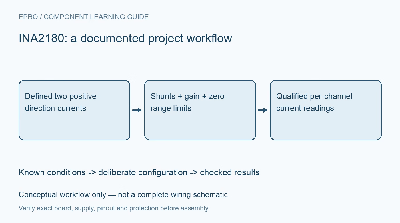
INA2180 Current Amplifier: 7 Checks for Two Unidirectional Channels
Use INA2180 dual current sensing with external Kelvin shunts, correct polarity, gain-dependent bandwidth and a practical low-current error budget. This is a documentation-based planning guide, not a report of independent hands-on testing.
1. Distinguish this dual device from a reference-input version
INA2180 provides two current-sense amplifier channels that use external shunts and ground-referenced outputs. It does not provide the independent reference terminals used by a bidirectional relative to center zero current above ground. Confirm the exact eight-pin package and symbol before copying a two-channel circuit. Define positive current direction for each shunt. If the application needs meaningful signed reverse-current measurement, choose an appropriate architecture rather than expecting a ground-referenced output to represent a negative voltage outside its usable swing. Manufacturer documentation.
2. Select gain and shunt from the allowed output range
Fixed-gain options are twenty, fifty, one hundred and two hundred volts per volt. Calculate shunt voltage and amplifier output at maximum intended current, then compare them with output headroom and ADC range. Include shunt tolerance, temperature coefficient, pulse capability and power dissipation. A larger gain improves the signal from a small shunt voltage but narrows the accepted input range. Keep the two channels separate in the calculations because different loads or shunts can have different thermal and uncertainty limits despite sharing one package. Manufacturer documentation.
3. Respect supply and bus common-mode limits separately
The amplifier supply operates from 2.7 V to 5.5 V, while the documented common-mode range is negative 0.2 V to 26 V. That wider input capability does not establish galvanic isolation or unrestricted input transient tolerance. Review each bus state, including controller power-off and source sequencing. Check downstream ADC limits independently from the bus voltage. A valid high-side sensing condition does not mean every surrounding signal connection remains safe if the amplifier and controller supplies are in different states. Manufacturer documentation.
4. Route each Kelvin connection away from load-current drop
Take separate sense connections from the shunt terminals rather than measuring a convenient length of power copper. Confirm polarity and avoid shared return voltage becoming part of the measured differential input. Follow the manufacturer input-filter guidance if filtering is required, including the effect of series resistance on gain. Match the layout and resistor construction to the error budget. A clean schematic differential pair cannot remove a voltage error introduced before those traces leave the actual current-carrying resistor. Manufacturer documentation.
Newest in the store


5. Define what zero and reverse current mean in the data
Near zero, offset and the lower output-swing limit affect what the ADC sees. An output close to ground is not proof of exactly zero current, nor does it quantify current flowing in the reverse direction. Specify a low-current uncertainty or detection threshold appropriate to the application. Do not subtract an arbitrary software offset and then claim full bidirectional performance. Use known input conditions to determine an accepted zero policy and identify over-range or unsupported-polarity records instead of silently reporting them as valid zeros. Manufacturer documentation.
6. Budget error and response for the selected variant
The offset specification depends on common-mode conditions, and bandwidth depends on the gain option. Do not apply the smallest headline offset or fastest response to every operating state. Include gain error, drift, shunt heating, filter response and ADC uncertainty for each channel. Where both currents change quickly, define the settling requirement and sampling schedule rather than assuming simultaneous software collection makes the analog paths matched. Record the actual variant and filter network so timing and accuracy assumptions remain reviewable. Manufacturer documentation.
7. Qualify both channels with known current conditions
Check each channel separately for wiring, sign convention and scaling, then exercise simultaneous operation, startup and an allowed temporary over-range condition. Compare against an appropriate reference and record temperature and settling time. Preserve invalid or unsupported conditions explicitly in the data. No independent accuracy or transient measurements are claimed here. Keep the shunt values, gain suffix and zero-current policy with the project so later ADC, load or resistor changes trigger a targeted review rather than inheriting an unsupported measurement claim. Manufacturer documentation.
Related reading: INA2181 Current Amplifier: 7 Checks for Two Signed Channels.
Catalog note: The exact-part search did not return a matching Epro listing during preparation. Check the current catalog; this guide makes no price, availability or included-accessory claim.