


ADS131M08 ADC: 7 Checks for Complete Eight-Channel Packets

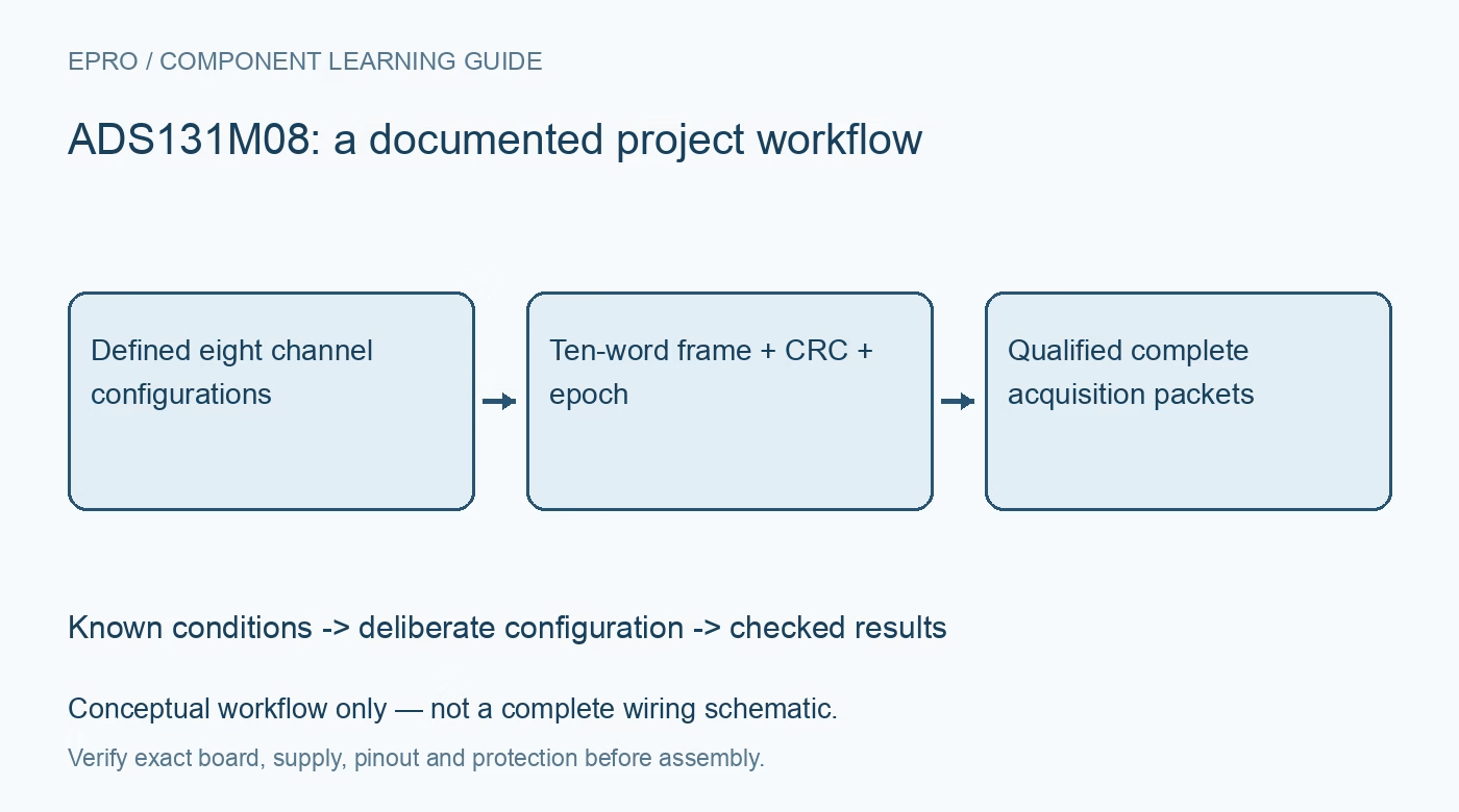
ADS131M08 ADC: 7 Checks for Complete Eight-Channel Packets
Build ADS131M08 acquisition with ten-word frames, channel configuration epochs, mandatory output CRC and deliberate FIFO recovery. This is a documentation-based planning guide, not a report of independent hands-on testing.
1. Define eight channels as a versioned acquisition setup
ADS131M08 simultaneously converts eight differential channels and supports a documented output rate up to thirty-two kilosamples per second. Record each input source, gain, phase setting and calibration state before enabling the sample loop. Simultaneous conversion does not eliminate different sensor bandwidths or phase responses. Twenty-four-bit codes also do not guarantee twenty-four-bit application accuracy. Establish safe input conditioning, common-mode limits and electrical protection independently rather than treating the converter as an isolated measurement front end for a high-energy installation. Manufacturer documentation.
2. Allocate the normal frame as ten device words
For most commands, the output frame contains the preceding command response, eight channel words and one CRC word. That is ten words, not the frame length of a smaller channel-count relative. Compute transfer duration from the selected sixteen-, twenty-four- or thirty-two-bit communication format and leave adequate host scheduling margin. Register commands can require different lengths, so separate them from the regular conversion parser. A transfer that ends early may return plausible values for initial channels while silently losing the remaining data-quality information. Manufacturer documentation.
3. Keep command response and conversion epoch distinct
The first output word answers the command from the previous input frame, not necessarily the command being transmitted at that instant. Model the response pipeline explicitly when changing configuration or reading registers. Tag accepted conversion packets with the configuration epoch that produced them, rather than applying the newest software settings retroactively to already queued data. If a transaction is interrupted, reestablish known communication and register state before continuing. A valid numeric sample is not enough to prove its gain and channel interpretation are current. Manufacturer documentation.
4. Validate CRC without assuming it prevents writes
The output CRC always appears at the end of the frame and cannot be disabled. Input CRC is separately configurable, and a WREG command still executes even when its input CRC check fails. Consequently, a reported write error does not prove the original configuration was preserved. Use the documented polynomial choice and FFFFh initialization, verify packet coverage and read back affected registers after a failed write. Keep packet integrity and configuration integrity as separate conditions in the accepted acquisition record. Manufacturer documentation.
Newest in the store


5. Decode signed channel data before scaling or calibration
The selected word width changes how conversion bits are truncated or padded. Decode signed data according to the actual interface configuration, then apply gain and calibration consistently across all eight channel positions. Preserve raw codes long enough to diagnose sign, byte-order and channel-offset errors. Use known safe inputs to establish polarity and range rather than trusting an internal test signal as complete external-chain calibration. An eight-channel record should explicitly identify invalid channels instead of replacing their values with an apparently measured zero. Manufacturer documentation.
6. Recover FIFO continuity after missed service intervals
The data mechanism has a two-deep FIFO, so pausing host reads can leave queued samples whose age does not match the time of the next SPI transfer. Follow the specified synchronization or prompt double-read recovery procedure and mark the interruption. Observe SYNC/RESET pulse requirements because the function depends on timing. Do not stitch data around a pause into a continuous waveform merely because subsequent packets pass CRC. Packet correctness and uninterrupted sample timing are different requirements for phase or spectral analysis. Manufacturer documentation.
7. Accept only complete packets with known provenance
Exercise a normal scan, a deliberate missed read, an interrupted configuration write and a controller restart with safe signals. Require the expected ten-word format, valid CRC, known command pipeline and accepted configuration epoch before releasing a packet to application calculations. Qualify analog accuracy separately from these digital checks. No independent noise, timing or metrology results are claimed here. Retain raw packet examples and recovery flags so a later analysis can distinguish complete eight-channel evidence from values that only look electrically plausible. Manufacturer documentation.
Related reading: ADS131M06 ADC: 7 Checks for Six-Channel Phase Records.
Catalog note: The exact-part search did not return a matching Epro listing during preparation. Check the current catalog; this guide makes no price, availability or included-accessory claim.