


INA300 Current Comparator: 7 Checks for Shunt Thresholds and Latched Alerts

INA300 Current Comparator: 7 Checks for Shunt Thresholds and Latched Alerts
Set INA300 shunt thresholds with its 20-microamp limit source, delay-dependent noise adjustment, hysteresis and deliberate alert reset timing. This is a documentation-based planning guide, not a report of independent hands-on testing.
1. Identify a comparator, not an analog current monitor
The INA300 compares a shunt differential voltage against a programmed limit and reports an alert. It does not provide an amplified analog current-output voltage for an ADC. Its supply range is 2.7 to 5.5 volts, while the specified input common-mode range is zero to 36 volts. Check both input terminal conditions rather than treating the common-mode capability as an isolated-current rating. Start with a protected low-voltage resistive load and a clearly defined positive current direction. Manufacturer documentation.
2. Translate current into shunt voltage and heating
Choose the shunt from the intended trip current, allowable voltage drop and dissipation. The nominal relation is shunt voltage equals current times resistance; shunt power is current squared times resistance. Include tolerance, temperature coefficient, terminal resistance and layout error. Kelvin sense connections help prevent load-current copper drops from becoming an unintended part of the threshold. Do not select a shunt solely to make the arithmetic convenient: it must survive the bounded fault interval and remain suitable for normal continuous operation. Manufacturer documentation.
3. Use the INA300 limit-source value and correction
The internal LIMIT source is nominally 20 microamps. Do not import an 80-microamp programming equation from another current comparator. At the ten-microsecond response setting, TI applies a 500-microvolt noise adjustment factor when calculating the limit resistor. For an intended 100-millivolt shunt threshold, the nominal expression is (0.100 + 0.0005) volts divided by 20 microamps, or 5025 ohms. This arithmetic is illustrative; source tolerance, offset and resistor tolerance still require an error budget. Manufacturer documentation.
4. Match noise adjustment to the response-time selection
Selectable response settings are ten, fifty and one hundred microseconds. The 500-microvolt adjustment applies to the ten-microsecond setting, not indiscriminately to every mode. TI explains that averaging in the longer settings removes the same correction requirement. A longer setting can reject short disturbances but also delays a genuine indication. Document the DELAY connection and guaranteed timing conditions. Do not describe a comparator response setting as the total time required for software, a power switch and the load to become safe. Manufacturer documentation.
Newest in the store


5. Set hysteresis and mode pins explicitly
Selectable hysteresis changes the return threshold and prevents chatter around the limit; it does not eliminate noise already coupled into the sense path. Follow the mode tables for low, high and open pin states rather than guessing how an unconnected configuration pin behaves. Likewise, define ENABLE during startup and sleep. Keep the sense filter and source impedance within the manufacturer guidance, because mismatched series impedances can introduce offset. Evaluate both increasing and decreasing current when checking the final trip behavior. Manufacturer documentation.
6. Distinguish transparent release from latch clearing
ALERT is an active-low open-drain output and needs a suitable pullup. LATCH low selects transparent operation; LATCH high retains an overlimit event. Clearing a retained event requires LATCH low for at least 20 microseconds, with the input condition back below the relevant threshold. A short generic logic pulse is not an adequate reset specification. If the fault persists, ALERT remains low. Verify the pullup voltage limit and the controller input threshold instead of assuming an unasserted open-drain pin creates its own high level. Manufacturer documentation.
7. Qualify the indication and the separate protection path
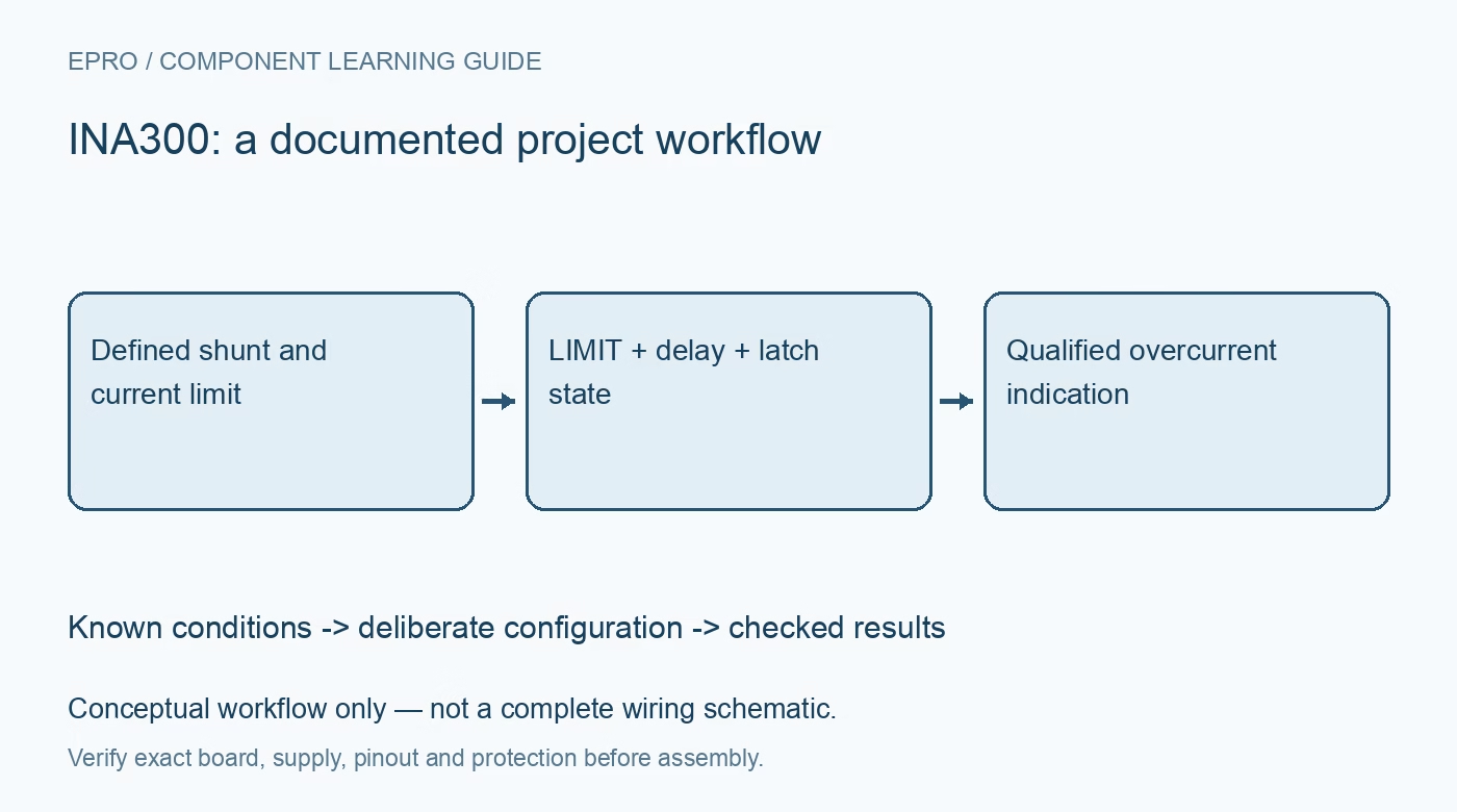
Record shunt resistance, programmed limit, response setting, hysteresis, pullup and reset timing together. Sweep a bounded low-voltage load above and below the threshold and distinguish expected behavior from measured trip points. Log alert detection and any subsequent shutdown separately. The comparator does not interrupt current by itself, and a latched indication is not proof that power was removed. Use an independently appropriate current-limited source and protection arrangement while validating the complete response chain. Manufacturer documentation.
Related reading: INA381 Current Monitor: 7 Checks for Comparator Routing and Alert Timing.
Catalog note: The exact-part search did not return a matching Epro listing during preparation. Check the current catalog; this guide makes no price, availability or included-accessory claim.