


LDR Sensor: 7 Buying Checks for Light Sensing

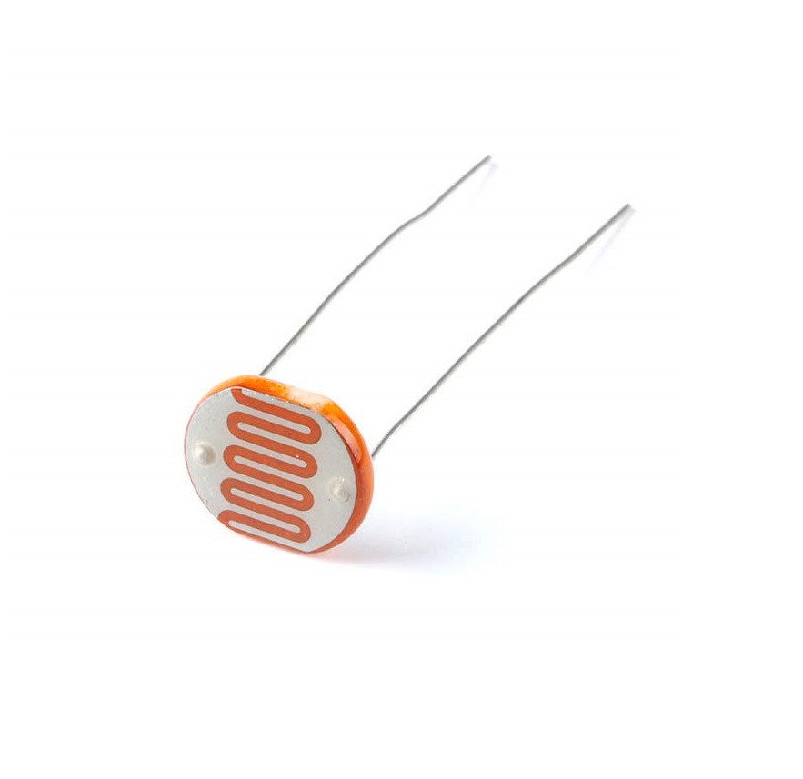
An LDR sensor is a light-dependent resistor whose resistance changes with illumination. It can be a simple introduction to analog sensing, but a bare photoresistor, a comparator module and a complete light switch are different products. Choose the part that matches the circuit you intend to build.
This guide focuses on low-voltage electronics learning projects. It does not provide household mains wiring instructions or claim that a generic photoresistor is a calibrated lux meter.

LDR sensor prices and package types
| Listed item | Price (PKR) | Project role |
|---|---|---|
| Photoresistor 5MM LDR Sensor in Pakistan | 12 | 5 mm bare photoresistor listing |
| Large 20mm LDR Photoresistor Sensor Photo Sensor in Pakistan | 55 | Larger 20 mm photoresistor listing |
| 3pin Photosensitive Sensor Module Light- Dependent Control LM393 LDR Module | 120 | Three-pin threshold comparator module |
Price snapshot: Epro listings checked on 18 October 2026. Confirm the current price, availability, delivery charges and package quantity on the linked page before ordering. These are dated listing prices, not a quotation or an independent performance test.
The 5 mm LDR needs supporting circuitry to produce a useful analog voltage. The three-pin LM393 light module instead describes a threshold output arrangement. A complete mains-powered sun switch is not an interchangeable component for either tutorial.
1. Decide between analog level and a threshold
A bare photoresistor used in a voltage divider can provide a continuously varying voltage. A comparator module can report whether the light crosses an adjustable threshold. A three-pin module should not be assumed to expose a separate analog output simply because another four-pin version does.
If the project needs a graph of relative brightness, confirm an analog signal is available. If it only needs a light-or-dark event, a threshold module may be sufficient. Neither output automatically carries calibrated lux information.
2. Understand the resistance change
A typical LDR has lower resistance in brighter light and higher resistance in darkness. The numerical resistance depends on the actual device, light source and conditions. Do not treat a broad listing range as a precise transfer function for every sensor supplied.
The Adafruit photocell guide explains why an LDR and a fixed resistor form a useful divider. The output is nonlinear with brightness, and individual sensors can differ. That makes calibration and realistic labelling important.
3. Choose physical size for the mounting
A larger sensing head can change the mechanical fit and viewing area, but diameter alone does not establish accuracy, sensitivity or response time. Check lead spacing, mounting clearance and whether the enclosure shades the sensor unintentionally.
Newest in the store


For an ambient-light demonstration, place the sensor where it sees the intended environment rather than a nearby indicator LED. A display or lamp controlled by the same system can illuminate the sensor and create feedback if placement is not considered.
4. Budget for the voltage-divider resistor
A bare LDR is a resistor, not a voltage source. A suitable fixed resistor and safe supply create a measurable node voltage. A 10-kilohm resistor is a common starting point for a beginner demonstration, but the best range depends on the intended light conditions and actual sensor resistance.
If the analog reading stays near its ceiling in bright conditions, the resistor choice may provide poor discrimination there. Select the circuit deliberately instead of assuming a single resistor value covers all illumination levels equally well.
5. Verify controller voltage compatibility
Keep the divider output within the analog input’s permitted range. A divider powered from 5 V must not automatically be connected to a 3.3 V-only ADC. A comparator module’s output level also depends on its actual design and pull-up arrangement, not just the threshold setting.
The three-pin module listing specifies a supply range including 3.3 V and 5 V. Confirm the actual board and controller requirements before choosing a supply. Do not interpret a bare component’s catalog maximum-voltage claim as permission to use a solderless breadboard on mains.
6. Separate sensing from switching loads
The sensor output is not intended to power a lamp, relay coil or motor directly. A larger load needs an appropriate driver and power design. Start with a controller’s built-in LED so the sensing behaviour can be observed without introducing another subsystem.
A complete mains light-control product belongs to a different installation workflow. This guide does not adapt a low-voltage LDR circuit into an exposed household switching project.
7. Calibrate for the real location
Observe readings in the actual bright and dark conditions before choosing a threshold. Add hysteresis if a value near the threshold causes rapid toggling. The LDR sensor Arduino voltage-divider guide shows a low-voltage test and explains why raw ADC counts should not be labelled lux without a suitable calibration model.