


OPA392 Precision Op Amp: 7 Checks for Noise Bandwidth and ADC Settling

OPA392 Precision Op Amp: 7 Checks for Noise Bandwidth and ADC Settling
OPA392 checks for package-specific offset, integrated noise, rising and falling settling, output loading and input overdrive. This is a documentation-based planning guide, not a report of independent hands-on testing.
1. Select the exact precision specification
The OPA392 is the single-channel member of the OPAx392 family, operating from 1.7 V to 5.5 V. The electrical table distinguishes package and family variants, so a ten-microvolt offset headline cannot be applied blindly to every ordering code, common-mode point or temperature. Preserve the full part identity and relevant conditions in the error budget. Rail-to-rail operation describes supported ranges, not zero error or unlimited output swing at both rails under every load. Manufacturer documentation.
2. Include common-mode and temperature in offset error
The table provides different offset limits near the positive rail and over temperature, including package-specific exceptions. An input that moves close to a rail can therefore have a different precision budget from one held near mid-supply. Define the complete common-mode trajectory as well as the signal excursion. Combine amplifier offset and drift with resistor, reference and source errors. Do not label a complete ADC front end as ten-microvolt accurate merely because its amplifier has that conditional maximum in one table row. Manufacturer documentation.
3. Integrate noise over the actual measurement bandwidth
The 4.4 nanovolt-per-root-hertz headline applies at 10 kHz under stated conditions; it is not the total output-noise voltage. Low-frequency noise, source resistance, current noise, closed-loop gain and the effective filter bandwidth all contribute. Rail-adjacent noise behavior can also differ. Choose a bandwidth that supports the required signal and settling, then calculate or characterize its integrated noise. A narrow displayed trace from a bandwidth-limited instrument does not establish the broadband noise delivered into the ADC acquisition network. Manufacturer documentation.
4. Compare settling accuracy with the ADC requirement
The detailed table gives typical settling figures for a specified two-volt step and unity gain, including 0.75 microseconds to 0.1 percent and a different interval for 0.01 percent. Those are not universal conversion-ready delays for an arbitrary ADC. A 0.1 percent residual can exceed a half-LSB target for a twelve-bit full-scale step. Define the allowed error fraction, step size, closed-loop gain, source and load before choosing acquisition time. Verify both step directions rather than assuming identical behavior. Manufacturer documentation.
Newest in the store


5. Separate bandwidth and slew from loaded acquisition
The 13 MHz gain-bandwidth figure and slew-rate values describe different response limits. The table also distinguishes rising and falling slew behavior. Capacitive loading, isolation resistance and an ADC’s switched sampling input can alter overshoot and final settling even when nominal bandwidth appears generous. Evaluate the actual closed-loop network and receiver model. Do not import a capacitive-load guarantee from another family member or a lower-power amplifier simply because the device names look related. A circuit can avoid oscillation yet still miss its sampled accuracy target. Manufacturer documentation.
6. Keep overdrive and output-current claims bounded
The high output-current figures are short-circuit characteristics, not a promise of continuous precision power delivery at the rails. Check output headroom and dissipation at the intended load. Input-bias current is typically very small, but maximum values and temperature matter, and overdrive can increase current through input protection structures when the feedback loop cannot remain linear. Include startup and saturation scenarios in the review. Board contamination, protection leakage and probe loading can dominate a high-impedance input long before the typical femtoamp figure becomes relevant. Manufacturer documentation.
7. Qualify the whole interface rather than one amplifier number
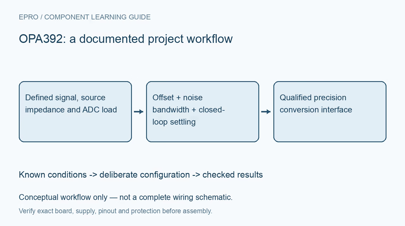
Record exact part, supply, common-mode range, source impedance, gain, filter, ADC sampling pattern, load and accepted settling error. Compare both directions of representative steps and inspect the actual sampled result after saturation recovery. The typical 1.22 mA quiescent current is only part of the system budget; feedback networks and output drive add demand. The acceptance record should establish bounded noise and acquisition performance while identifying offset, reference error, leakage, overdrive and timing as distinct contributors requiring their own evidence. Manufacturer documentation.
Related reading: OPA391 Precision Buffer: 7 Checks for Low Bias and Real Error Limits.
Catalog note: The exact-part search did not return a matching Epro listing during preparation. Check the current catalog; this guide makes no price, availability or included-accessory claim.