


REF6225 Buffered Reference: 7 Checks for Temperature Range and Burst Accuracy

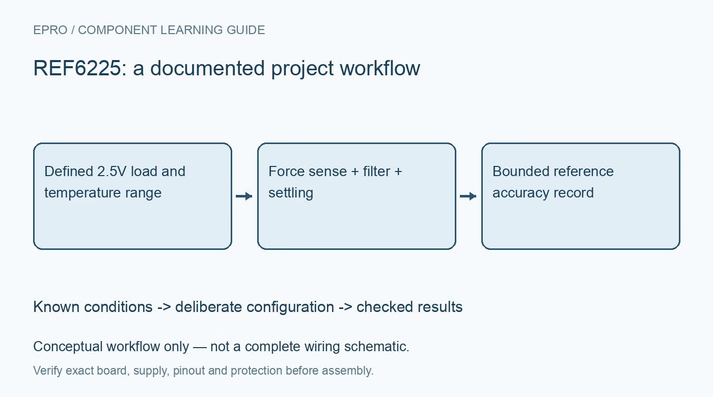
REF6225 Buffered Reference: 7 Checks for Temperature Range and Burst Accuracy
Plan REF6225 reference paths with the actual 0–70°C rating, Kelvin routing, current-limit settings, capacitor requirements and burst-load checks. This is a documentation-based planning guide, not a report of independent hands-on testing.
1. Keep the specified temperature range visible
REF6225 is a buffered 2.5V precision reference whose recommended operating-temperature range is 0°C to 70°C. Do not copy a wider industrial range from a related reference just because the architecture looks similar. The low-drift headline is specified over the stated interval. Identify the exact ordering code and retain the source revision with the design record. A room-temperature prototype cannot establish behavior outside the recommended range or justify an outdoor installation without additional qualification. Manufacturer documentation.
2. Use the correct supply and load limits
The recommended REF6225 input range is 3V to 5.5V under the listed conditions. The buffered output supports a few milliamps of specified load, not an arbitrary sensor or logic supply. Include source tolerance, startup and current-limit configuration when checking headroom. Different members of the REF62 family have different nominal outputs and some different current limits. Select from the exact-part table rather than treating the entire family description as one interchangeable reference rail. Manufacturer documentation.
3. Preserve force and sense routing
OUT_F carries output current and OUT_S senses the voltage at the intended load point. GND_F and GND_S likewise separate current return from the quiet sense connection. Wire and route them according to the manufacturer application guidance; sense pins must not float or become substitute load-current conductors. Locate the converter reference and ground connections deliberately. A Kelvin arrangement only reduces relevant trace-drop errors if the PCB preserves the intended current paths instead of joining everything at an arbitrary noisy connector. Manufacturer documentation.
4. Treat filter and output capacitors as different components
The FILT connection and the output-load capacitor serve different functions. Use the documented minimum filter capacitance, output stability range and placement guidance rather than assuming one large capacitor can replace both. Check effective capacitance, leakage and dielectric behavior. The attractive noise and dynamic-impedance numbers are tied to stated capacitor conditions. Record the complete network with measurements so differences in reference droop or startup are not attributed to device variation when the actual circuits are different. Manufacturer documentation.
Newest in the store


5. Program SS as a current-limit function
The SS pin controls short-circuit current behavior; it is not a generic regulator soft-start capacitor input. Follow the manufacturer resistor or supply-connection guidance and review how the chosen setting affects recommended output loading. Protection current and useful precision drive capability are not the same specification. Avoid copying a similarly named pin circuit from an unrelated component. Verify the selected configuration with a protected source and a benign load before evaluating the converter reference under repetitive sampling. Manufacturer documentation.
6. Separate initial accuracy, drift and burst settling
The 0.05% initial-accuracy headline corresponds to 1.25mV at 2.5V before other system contributions. The stated 3ppm-per-degree temperature coefficient is a separate specification over its defined range, not an extra decimal-place guarantee at one temperature. First-sample precision examples also depend on the ADC, capacitor and burst conditions. Observe the actual reference during conversion activity and after the required startup interval. Do not generalize a documented ADS8881 example to every converter or every burst repetition rate. Manufacturer documentation.
7. Measure at the qualified load point
Use appropriate low-noise probing and instrumentation with known uncertainty at the actual converter reference connection. Compare idle, continuous-conversion and burst operation while logging supply, temperature, load pattern, capacitor network and warmup interval. Keep the first accepted conversion and any discarded startup samples identified. A stable multimeter value alone does not characterize dynamic impedance. The handover should describe one tested reference path and its uncertainty, clearly separated from documentation-based expectations or unsupported performance claims for untested modules. Manufacturer documentation.
Related reading: REF6025 Buffered Reference: 7 Checks for Kelvin Sense and the SS Pin.
Catalog note: The exact-part search did not return a matching Epro listing during preparation. Check the current catalog; this guide makes no price, availability or included-accessory claim.