


THVD1551 RS-485 Transceiver: 7 Checks for a Five-Volt Full-Duplex Link

THVD1551 RS-485 Transceiver: 7 Checks for a Five-Volt Full-Duplex Link
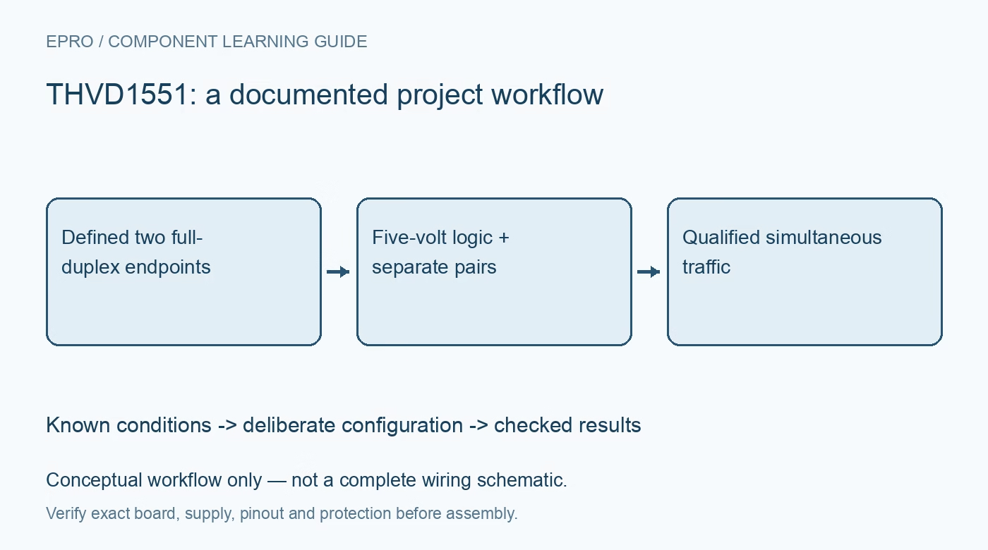
Design THVD1551 links around a five-volt supply, always-enabled transmit and receive paths, separate pairs and cable-level verification. This is a documentation-based planning guide, not a report of independent hands-on testing.
1. Identify the full-duplex device without enable controls
THVD1551 uses separate driver and receiver pairs and has no external driver-enable or receiver-enable terminals. It is not the half-duplex family member with DE and active-low receiver control. Establish fixed ownership of the driven cable pair before preparing a network diagram. Firmware cannot release this driver through a nonexistent enable pin. If a system needs multiple transmitters on one shared pair, the chosen architecture must address that requirement rather than borrowing a two-wire multidriver protocol unchanged. Manufacturer documentation.
2. Design for the actual five-volt supply requirement
The recommended supply is 4.5 V to 5.5 V. A related transceiver supporting operation from three volts does not establish the same range for this device. Check minimum voltage at the package during startup and simultaneous traffic, including regulator tolerance and wiring drop. Provide local bypassing according to the layout guidance. A five-volt rail name on the schematic is not evidence that the voltage remains within range when a long supply lead or another load produces a transient. Manufacturer documentation.
3. Separate logic compatibility from bus voltage capability
Check the transmit input and receive output specifications against the actual processor. In particular, a five-volt transceiver output is not automatically safe for a processor whose inputs tolerate only its lower supply. Include processor power-off behavior and any level translation. The extended bus common-mode range refers to the differential interface environment, not to unrestricted voltage on logic terminals. Keep controller-side limits and cable-side limits as separate checks in the design review rather than treating robust RS-485 signaling as universal voltage tolerance. Manufacturer documentation.
4. Verify pair direction and polarity at both ends
Y and Z are transmitter outputs, while A and B feed the receiver. Draw each endpoint transmitter driving the other endpoint receiver, including the reference connection and polarity. Connector labels can be inconsistent across equipment vendors, so verify the electrical truth table rather than matching letters alone. Use distinguishable patterns to confirm both directions independently. A link that receives one message after swapping wires is not yet documented well enough for repeatable installation or replacement of one endpoint. Manufacturer documentation.
Newest in the store


5. Terminate the real topology and budget timing
Treat each full-duplex pair as its own transmission line, with termination based on cable impedance and actual driven direction. Avoid adding identical termination networks at every connector without considering the topology. The fifty-megabit capability depends on loading and timing conditions; cable delay, branches and protection capacitance still matter. Include driver and receiver delays in the controller timing budget. A successful low-data-rate message on a short bench cable does not demonstrate adequate margin for the planned cable length or signaling speed. Manufacturer documentation.
6. Keep ESD and loading claims in their proper scope
The family specifies strong bus-pin ESD performance and an extended operational common-mode range. These are defined device characteristics, not galvanic isolation or a guarantee against every field surge. Likewise, use the exact family loading entry for this device instead of copying a different relative node count; the DC load model is not a complete practical network-size guarantee. Evaluate ground differences, surge exposure and the capacitance of any external protection as a system before accepting an industrial cable interface. Manufacturer documentation.
7. Qualify simultaneous traffic and endpoint power changes
Send separate patterns in both directions and verify that the receiver processing remains correct during simultaneous transmission. Exercise endpoint reset, cable disconnection and loss of supply in a safe arrangement, observing whether the always-active driver creates an unwanted system state. Record cable, termination, supply and logic-interface details with the results. This guide reports no independent bit-error or transient-survival measurements. Keep actual installation evidence distinct from manufacturer ratings so later topology changes can be reviewed against a known qualified link. Manufacturer documentation.
Related reading: THVD1451 RS-485 Transceiver: 7 Checks for Full-Duplex Links.
Catalog note: The exact-part search did not return a matching Epro listing during preparation. Check the current catalog; this guide makes no price, availability or included-accessory claim.