


24V to 5V Buck Converter: 7 Power Checks

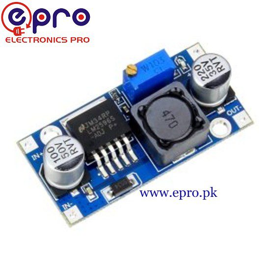
Last checked: 18 October 2026. Any prices below are dated Epro listing examples, not guaranteed current quotations. Confirm the exact model, stock and package before ordering.
A 24V to 5V buck converter can supply a suitable 5V electronics circuit from a higher-voltage DC source. Getting the meter to display 5.0V is only the start: startup peaks, wiring drop, ripple and connector behavior can determine whether the device works reliably.

This is a low-voltage DC guide, not a direct mains wiring tutorial. A bare regulator board is not automatically a compliant USB charger, a complete Raspberry Pi power supply or an industrially certified power module.
1. Check the 24V source before selecting a module
Identify whether the input is a regulated adapter, a battery system or a supply shared with motors. A nominal 24V battery changes voltage while charging and discharging. Shared machinery can create disturbances that a simple hobby board was not designed to tolerate. Choose the required input range and environmental ratings from the real source.
2. Calculate the 24V to 5V buck converter load
A device needing 5V at 2A requires 10W at the output. With an illustrative 85% efficiency, input power would be about 11.8W, or about 0.49A from a steady 24V source. These numbers are a worked example, not a guaranteed operating point for any particular Epro module.
Include attached peripherals and startup demand. A small controller may briefly draw more current when a radio transmits or another component starts. A supply that handles the average load can still produce resets if it cannot support those peaks.
3. Verify the device’s acceptable voltage range
Different 5V products have different tolerances and input arrangements. Read the manufacturer’s power specification and identify the correct input connector or pin. An ESP32 development board may have a board-specific 5V input, but the microcontroller’s 3.3V rail must not be fed with 5V. See the ESP32 power and GPIO checks before connecting it.
4. Include cable and connector voltage drop
The converter can measure correctly at its output while the device receives too little voltage through a long or poor-quality cable. Measure at the load during operation. Improve the cable, connector and wiring arrangement rather than blindly increasing the regulator voltage above the device’s permitted input.
Keep power conductors appropriately sized, short where practical and securely terminated. Do not use loose signal jumpers or a solderless breadboard as the distribution path for a high-current 5V load.
Newest in the store


5. Check ripple and startup behavior
A digital multimeter does not show every short spike or ripple waveform. Sensitive devices may need evaluation with an oscilloscope and the manufacturer’s recommended probing method. Extra output capacitors are not a universal cure; stability and startup behavior depend on the regulator design and supported capacitance.
The LM2596 manufacturer’s reference describes an example step-down regulator family. Its documentation cannot establish the performance of every module sold under the same chip name. Review the actual board’s parts, layout and thermal limitations.
6. Treat USB as more than two power wires
A plain 5V output does not automatically implement USB-C current advertisement, USB Power Delivery or other charging protocols. Some devices and cables require correct interface behavior. Do not build an improvised charger for valuable electronics by assuming any USB-shaped connector makes the regulator compliant.
For a Raspberry Pi or similar computer, use the manufacturer’s recommended supply unless you can verify the complete alternative design. Requirements can change by model, peripheral load and connector. A successful idle boot is not a full power validation.
7. Set, load-test and thermally check the converter
Set the voltage with the final device disconnected, verify polarity and use an appropriately rated test load. Check output under load, then temperature in the intended enclosure. Epro’s LM2596 module — PKR 180 is a checked listing example, not an assurance that it can continuously power any 5V computer.
For module comparisons, use the buck converter buying guide. For practical adjustment steps, see the LM2596 setup workflow.
Common questions
Can I connect 24V directly to a board’s USB input?
No. USB power inputs must only receive voltages permitted by their implemented interface and specification.
Is a higher advertised current always safer?
No. Correct voltage, protection, thermal performance and interface behavior still matter. Compare verified operating conditions rather than only a headline number.