


ULN2003 Driver Board: 7 Checks for a 28BYJ-48 Motor

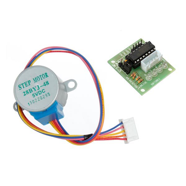
A ULN2003 driver board lets a controller switch the coils of a compatible unipolar stepper motor without supplying motor current directly from GPIO. The common 5 V 28BYJ-48 combination is useful for learning stepping sequences and low-speed geared movement.
Before buying, separate the bare driver IC from an assembled board and motor package. Those are different purchases with different assembly requirements, even when they share the same driver name.

ULN2003 driver board packages and prices
| Listed item | Price (PKR) | Project role |
|---|---|---|
| ULN2003 IC DIP Stepper Motor Drive in Pakistan | 25 | Bare DIP driver IC; not a complete motor-and-board kit |
| 28YBJ-48 DC 5V 4 Phase 5 Wire Stepper Motor With ULN2003 Drive in Pakistan | 380 | Listed 5 V geared stepper motor with ULN2003 board |
Price snapshot: Epro listings checked on 18 October 2026. Confirm the current price, availability, delivery charges and package quantity on the linked page before ordering. These are dated listing prices, not a quotation or an independent performance test.
The motor-and-driver package lists one 5 V motor and one driver board. The bare ULN2003 IC needs an appropriate circuit and connections around it. The much lower IC price should not be compared as though it includes the complete kit.
1. Identify a unipolar motor interface
The listed motor uses a five-wire arrangement with a common connection and switched phase paths. That matches the usual ULN2003 board approach. A four-wire bipolar motor needs a different current-reversing drive arrangement and is not a drop-in substitute.
Verify the actual motor label, connector and board documentation. The Epro listing uses the name 28YBJ-48 in places; the familiar family is commonly written 28BYJ-48. Similar names do not justify ignoring the voltage printed on the supplied motor.
2. Understand what the driver actually does
The Texas Instruments ULN2003A datasheet describes a Darlington transistor array with low-side switching outputs and clamp diodes. It is not a programmable microstepping current-regulating driver or a full H-bridge.
Software must generate the phase sequence through the board inputs. A direction command alone has no meaning unless the application or library translates it into the appropriate sequence. Do not expect A4988-style STEP and DIR wiring on this board.
3. Match the motor supply voltage
The current kit listing is for a 5 V motor. Other members of the family can have different voltage ratings. A driver IC’s high collector-voltage capability does not permit applying that voltage to a motor rated for 5 V.
Newest in the store


Use an appropriately regulated motor supply and suitable wiring. Share the intended ground reference with the controller, but do not feed the motor from a GPIO. If the controller is USB-powered, plan the power arrangement without casually joining independent positive supply rails.
4. Review current and heating together
A single-output current rating from the IC datasheet is not a promise that every channel can carry that figure simultaneously on a small module. Package dissipation, the number of energized coils, duty cycle and board construction all matter.
The Darlington outputs also have a voltage drop, so not all supply voltage necessarily appears across a coil. Check actual behaviour under load and stop if heating is unexpected. Do not compensate for poor torque by arbitrarily increasing the motor supply above its rating.
5. Distinguish full steps, half steps and output angle
A stepper library can use different excitation sequences. Full-step and half-step counts therefore differ. The motor’s gearbox further changes the relationship between electrical steps and output-shaft rotation.
The commonly quoted 2048 and 4096 counts are nominal figures associated with particular stepping assumptions and an approximately 64:1 reduction. They should not be treated as a calibrated guarantee of exactly one shaft revolution for every variant. Measure the actual assembly if angle matters.
6. Account for backlash and lost steps
A geared educational motor has mechanical limits. Reversing direction can expose gearbox backlash, and excess load or speed can cause missed steps. A software position counter records commanded motion, not independent confirmation of where the shaft actually moved.
Use a modest unloaded test first. A system requiring repeatable reference position needs a suitable homing or feedback plan. This kit is not a certified positioning or safety device, and a gear reduction should not be assumed to hold every load securely when power is removed.
7. Choose the library after the hardware
Follow the ULN2003 Arduino wiring and 28BYJ-48 code guide for a short half-step movement test. Confirm the input order and actual motor rotation before adding an enclosure, load or speed requirement. The first goal is a correct sequence, not the highest possible advertised RPM.