


ACS712 Current Sensor: 7 Buying and Calibration Checks

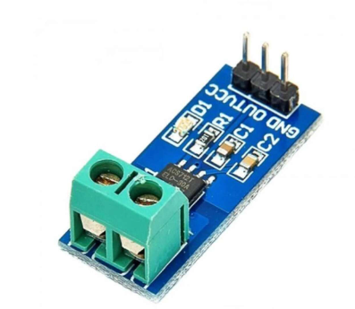
An ACS712 current sensor uses the Hall effect to produce an analogue signal related to current. It is not a ready-calibrated digital ammeter, and the 5 A, 20 A and 30 A versions do not use the same conversion constant.
A good purchase starts with the exact chip variant and the construction of the supplied board. This guide is aimed at small, protected low-voltage DC learning projects. It does not provide instructions for connecting a hobby module to household mains.

ACS712 current sensor prices and package checks
| Listed item | Price (PKR) | Project role |
|---|---|---|
| ACS712 Range Current Sensor Module of 5A, 20A, 30A in Pakistan | 320 | Range-selection module listing; verify the selected option |
| 30A Current Sensor ACS712 SMD in Pakistan | 480 | 30 A SMD product listing; confirm the actual supplied package |
Price snapshot: Epro listings checked on 18 October 2026. Confirm the current price, availability, delivery charges and package quantity on the linked page before ordering. These are dated listing prices, not a quotation or an independent performance test.
The displayed price on the 5 A, 20 A and 30 A range listing is not proof that all options have identical availability or price. Check the selected variation before checkout. The 30 A SMD listing also needs a package check rather than an assumption that a particular terminal-board assembly is included.
1. Read the part marking, not only the headline
Confirm whether the supplied part is the 5 A, 20 A or 30 A variant. Product descriptions can combine information about several versions. If a listed sensitivity conflicts with the actual device marking, resolve that mismatch before writing the conversion code.
The Allegro ACS712 datasheet is the appropriate reference for the device’s nominal characteristics. A generic module paragraph should not override the variant-specific table.
2. Use the correct nominal sensitivity
| Variant | Nominal sensitivity at 5 V |
|---|---|
| 5 A | 185 mV/A |
| 20 A | 100 mV/A |
| 30 A | 66 mV/A |
These are nominal starting values, not a calibration record for your module. Using 66 mV/A in code for a 5 A part can create a large scaling error even though the displayed current changes when a load is connected.
Choose a range appropriate to the expected measurement and required resolution. A higher current headline does not automatically make a better instrument for a small load; the smaller output change per ampere can be harder to distinguish from noise and ADC uncertainty.
3. Keep supply and analogue input limits separate
The ACS712 is a nominal 5 V device, with a specified 4.5–5.5 V supply range. At zero current, its output is around half the supply voltage. With current in one direction the output rises; in the other it falls.
Newest in the store


That behaviour matters when using a 3.3 V controller. A midpoint that appears acceptable at no load does not prove the maximum output is safe for that ADC. Review the complete signal range and an appropriate interface before connecting a different controller.
4. Distinguish chip isolation from board safety
The datasheet’s isolation specification for the IC does not certify the breakout board, screw terminals, wiring or enclosure for mains use. A current-range marking also does not establish the safe continuous current of the complete assembly.
For a first experiment, use only a small current-limited or otherwise appropriately protected source of no more than 5 V DC and a suitable low-power load. Do not carry high current through a solderless breadboard or use this guide as a household-energy-meter installation procedure.
5. Calibrate zero without removing the sensor supply
Measure the no-current output while the sensor itself remains powered. The primary load circuit must have no current during this step. Taking zero with an operating load subtracts that real load from later readings and can make the result misleading.
Zero offset can vary with temperature and module conditions. Averaging several samples reduces some random fluctuation, but it does not correct every offset, sensitivity error or reference-voltage error. Compare a known small DC current against a suitable reference instrument.
6. Do not label a DC average as AC RMS
A simple average is useful for a steady DC demonstration. Alternating positive and negative excursions can average towards the midpoint, so that calculation is not an AC RMS measurement. An AC instrument requires a suitable sampling, bandwidth and calibration design.
Similarly, taking the absolute value of every result is not a universal calibration fix. Negative current may represent direction, while a small negative reading at zero may be offset or noise that should be investigated.
7. Start with a limited bench demonstration
The ACS712 Arduino low-voltage DC guide explains signal wiring, no-current calibration and an explicitly nominal conversion. Verify the exact part first, power down before changing the primary wiring and keep the experiment away from mains and hazardous loads.