


DRV8825 Stepper Driver: Current Limit and Carrier Selection

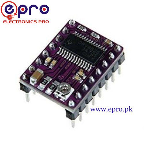
The DRV8825 drives a bipolar stepper motor using two regulated H-bridges and a STEP/DIR interface. A small carrier board is convenient, but its continuous current capability is not established by the IC headline rating. Selection starts with motor phase current, the actual carrier circuit, cooling and a suitable protected motor supply.
Confirm motor and driver compatibility

Identify two separate motor coil pairs with the motor disconnected and power removed. A normal bipolar four-wire motor is the intended type. Do not connect a five-wire unipolar motor unchanged simply because it is described as a stepper. Check rated phase current, winding arrangement and the mechanical load before choosing a carrier.
Choose supply voltage within complete-board limits
TI specifies an 8.2–45 V operating supply range for the IC, but a carrier’s capacitors and other parts can impose narrower limits. Stay within the documented range for the actual board and allow margin for transients. Local bulk capacitance and short power wiring matter because lead inductance can produce damaging voltage spikes.
Calculate the current limit from the actual sense resistor
The manufacturer relationship is IFS = VREF / (5 × RSENSE). Read the installed sense-resistor value and the carrier documentation before applying it. As an illustrative calculation, a confirmed 0.10 ohm resistor and 0.50 V reference correspond to 1.0 A full-scale. This is not a universal setting for every purple carrier or an instruction to use 1 A for every motor.
Do not confuse supply current with phase current
The driver regulates winding current while switching energy from the motor supply. A supply ammeter is not a direct measurement of each phase’s regulated current. Full-step current behavior also differs from the full-scale setting: the datasheet’s full-step sequence uses about 71% of full-scale in each phase. Use the carrier’s adjustment procedure and the motor’s limits.
Check microstep pins and mechanical expectations
The IC supports settings through 1/32 microstepping using MODE0–MODE2. Select modes from the documented table and keep inputs defined. More microsteps improve command granularity and can smooth motion, but they do not guarantee proportional position accuracy or increased torque. Required STEP pulse frequency rises for the same shaft speed.
Plan cooling and safe connections
Do not plug or unplug motor windings with the driver powered. Secure the carrier orientation, keep conductive tools away from exposed pins and follow a safe reference-voltage adjustment method. A heatsink alone does not establish a continuous current rating. Begin with an unloaded, mechanically restrained test and stop on abnormal heating, supply faults or unexpected motion.Newest in the store


Relevant Epro listing
Product information and prices were checked on 19 October 2026. This is a current snapshot, not a historical price associated with the publication timestamp. Stock, accessories and checkout prices can change. Listing claims are not independent performance or authenticity certifications.
| Product | Checked price | Stock |
|---|---|---|
| DRV8825 Stepper Motor Driver in Pakistan | PKR 560 | In stock |
Frequently asked questions
Is the same VREF correct for every carrier?
No. The sense resistor and carrier design determine the relationship. Confirm the actual board before adjustment.
Does 1/32 mode guarantee 32 times better position accuracy?
No. It increases command resolution; motor, load and current-control behavior still limit actual position accuracy.
Related Epro reading
Review breadboard connections before assembling a prototype. For controller expansion, the Mega 2560 pin guide explains why pin names and electrical limits must be checked together.
Technical references and test limitations
This guide uses the documentation linked below. The procedures are for a controlled, low-voltage learning setup; no independent hands-on test of the particular seller board is claimed. Record the actual part markings, wiring and firmware version before drawing conclusions from a test.