


MAX232 RS232 to TTL Converter: Choosing the Correct Interface

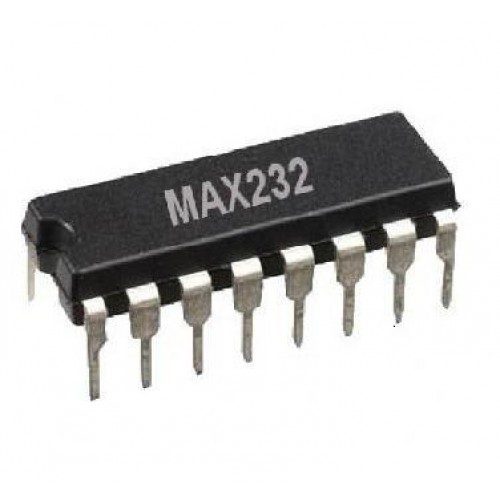
A MAX232 RS232 to TTL converter translates between logic-level UART signals and the different electrical levels used by a true RS232 port. It is not a USB converter or an RS485 transceiver. Choosing the right part prevents a connector or the word serial from being mistaken for electrical compatibility.
Identify the remote interface first

Confirm whether the equipment really uses RS232 rather than three-volt UART, five-volt UART, USB or RS485. A DB9 connector is not sufficient proof of signal type or pinout. Read the equipment manual before attaching an adapter, and do not connect an unknown serial line directly to a microcontroller GPIO.
Separate the IC from a complete module
The checked Epro MAX232 listing is an IC. A working circuit also needs the documented charge-pump capacitors, decoupling and appropriate connectors or wiring. A finished MAX3232 board is a different product and should not be assumed identical because a marketplace title mentions both names. Check the actual installed device and schematic.
Respect the five-volt requirement
The linked TI MAX232 specifies a nominal five-volt supply, with recommended operation from 4.5–5.5 V. Do not assume it works properly at 3.3 V because a MAX3232-family device may. Its logic-side receiver output also needs to be compatible with the host. Use an appropriate interface for a three-volt-only controller rather than relying on similar names.
Choose capacitors for the exact variant
The TI MAX232 application uses four 1 microfarad charge-pump capacitors plus supply bypassing. Some related parts use different values. Match the manufacturer and suffix, observe polarity where applicable, and use voltage ratings appropriate to the generated rails. Reusing a random schematic for a similarly named part can cause poor or failed operation.
Understand driver and receiver directions
Host TX feeds a logic-side driver input; the associated RS232 output goes toward the remote receiver. Remote RS232 TX enters an RS232 receiver input; its logic output feeds host RX. Cross transmit and receive according to signal roles, not by joining equal connector pin numbers or trusting one cable photograph.
Check connector roles and required handshakes
DTE/DCE roles and cable wiring determine whether a straight or crossed connection is appropriate. Some equipment needs hardware flow control or additional control lines that a minimal TX/RX interface does not provide. Match framing and baud settings as well. A correct voltage translator does not implement the remote device’s command protocol.
Newest in the store


Keep the first test isolated from important equipment
Use a documented adapter and a harmless loopback or test endpoint before connecting operational equipment. Confirm signal voltage, polarity and grounding. The MAX232 is not galvanically isolated by itself, so independently powered equipment can still introduce ground issues. Do not infer industrial safety from a short successful serial exchange.
Relevant Epro listing
Product information and prices were checked on 19 October 2026. This is a current snapshot, not a historical price associated with the publication timestamp. Stock, accessories and checkout prices can change. Listing claims are not independent performance or authenticity certifications.
| Product | Checked price | Stock |
|---|---|---|
| MAX232 dual EIA 232 drivers and receiver line bus driver IC | PKR 80 | In stock |
Frequently asked questions
Is MAX232 the same as a USB-to-UART adapter?
No. MAX232 translates UART electrical levels to/from RS232; USB requires a separate USB interface device.
Can every MAX232 circuit run at 3.3 V?
No. Check the exact part. The linked TI MAX232 is a five-volt device; similarly named alternatives have different specifications.
Related Epro reading
Review breadboard connections before assembling a prototype. For controller expansion, the Mega 2560 pin guide explains why pin names and electrical limits must be checked together.
Technical references and test limitations
This guide uses the documentation linked below. The procedures are for a controlled, low-voltage learning setup; no independent hands-on test of the particular seller board is claimed. Record the actual part markings, wiring and firmware version before drawing conclusions from a test.