


MP1584 Buck Converter: Small Module, Real Load Limits

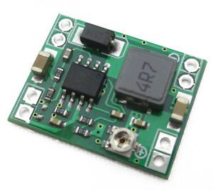
An MP1584 module steps a suitable DC voltage down to a lower output. Its small footprint is useful for a compact prototype, but it reduces the room available for heat spreading and connectors. Choose the complete board by the real source, load, output setting and thermal conditions rather than by the regulator IC’s headline current.
Confirm a step-down topology suits the source

A buck converter cannot maintain a target output above its input and needs appropriate operating headroom. Check the source’s full range, not just its nominal label. A battery that crosses above and below the desired output may require another topology. This ordinary module is not an isolated supply or a battery charger.
Separate IC capability from module rating
The referenced MPS documentation describes an IC with a 4.5–28 V input range and a nominal three-amp class capability under specified conditions. The checked Epro board is listed as a one-amp module. Do not silently upgrade that board to a guaranteed three-amp continuous output; its inductor, capacitors, layout, cooling and seller specification all matter.
Budget source and load power
Calculate output power from target voltage and expected current, including startup peaks. Input power must exceed that output by the conversion losses. The input-current reading is not generally the same as output current for a buck converter. Check wire losses and source limits before interpreting low output voltage as a need to turn the adjustment pot further.
Adjust with the load disconnected
Identify IN and OUT polarity from the actual board. Use a suitable current-limited source and voltmeter, set the target output at no load, then disconnect input before attaching the load. Trimmer direction and number of turns can vary. Never connect a sensitive five-volt device before measuring the actual output setting.
Validate under a modest representative load
Bring the load up conservatively within the documented board limit and measure voltage at both the module and the load. Watch for droop, instability, abnormal heating or a source current limit. A correct no-load voltage is not evidence of usable loaded performance. Stop and investigate rather than accepting repeated shutdown as normal regulation.
Plan mounting and failure consequences
Insulate the underside from metal, secure leads and allow airflow. A tiny module suspended from a power wire is not a durable installation. If overvoltage could damage the load, design appropriate independent protection; do not assume every inexpensive converter fails safely. Check the finished enclosure because temperature and wiring conditions differ from an open bench.Newest in the store


Relevant Epro listing
Product information and prices were checked on 19 October 2026. This is a current snapshot, not a historical price associated with the publication timestamp. Stock, accessories and checkout prices can change. Listing claims are not independent performance or authenticity certifications.
| Product | Checked price | Stock |
|---|---|---|
| Mini DC-DC Adjustable Step Down Buck Converter 1A MP1584 | PKR 145 | In stock |
Frequently asked questions
Does the IC’s three-amp description guarantee this board delivers three amps?
No. The checked board is listed as one amp; complete-board limits and thermal conditions must be respected.
Can it boost a lower input to a higher output?
Not as an ordinary buck module. Choose a topology suitable for the complete source and target range.
Related Epro reading
Review breadboard connections before assembling a prototype. For controller expansion, the Mega 2560 pin guide explains why pin names and electrical limits must be checked together.
Technical references and test limitations
This guide uses the documentation linked below. The procedures are for a controlled, low-voltage learning setup; no independent hands-on test of the particular seller board is claimed. Record the actual part markings, wiring and firmware version before drawing conclusions from a test.