


AD9833 DDS: 7 Clock and Output-Load Checks

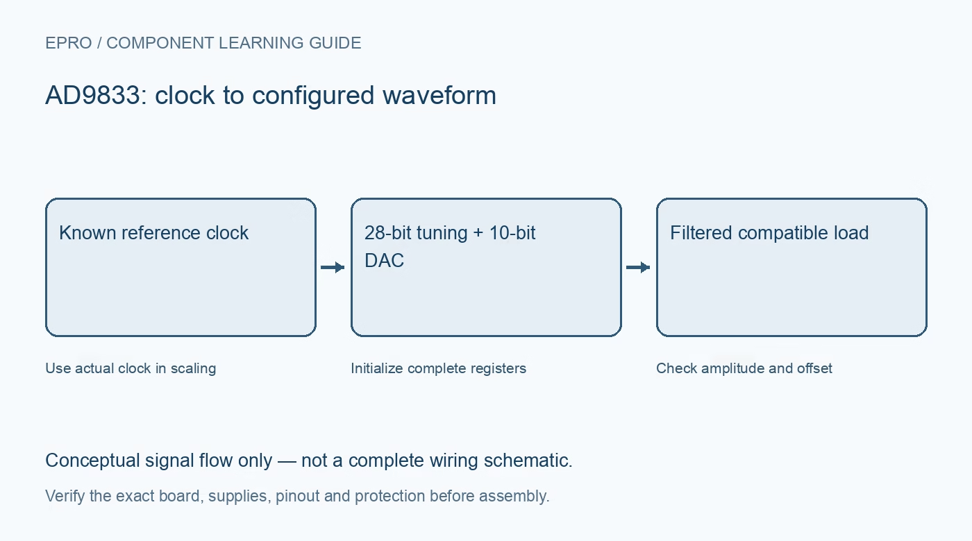
An AD9833 synthesizes periodic waveforms from a reference clock and digital configuration. A small module can be useful for a wired low-voltage bench experiment, but it is not automatically a calibrated signal generator or a power output stage. Verify the exact clock and analog circuit before choosing one.
Identify the clock and carrier circuit
Read the oscillator marking and carrier schematic, including power regulation and output buffering. The bare chip supports a 2.3 V to 5.5 V supply and a reference clock up to the documented limit. A board label does not establish its actual clock frequency, amplitude or host-interface voltage compatibility.
Understand frequency-word resolution
A twenty-eight-bit frequency word sets the ideal output frequency relative to MCLK. The increment is the clock frequency divided by two to the twenty-eighth power. This fine digital step is not guaranteed absolute frequency accuracy: oscillator tolerance, aging and clock quality still affect the actual output.
Separate DAC resolution from frequency tuning
The analog waveform uses a ten-bit DAC. The twenty-eight-bit tuning word does not provide twenty-eight-bit amplitude precision. Check the output specifications and distortion conditions separately instead of treating the frequency-register length as a guarantee of waveform amplitude accuracy or spectral purity.
Treat high-frequency headlines cautiously
The advertised upper output range is not a promise of a clean unfiltered sine wave at every frequency and load. Image components and reconstruction requirements matter as output frequency approaches a substantial fraction of the clock. Choose an intended low-frequency test point before evaluating a broad frequency sweep.
Check the actual output stage
The bare-device analog output is a small signal with its specified offset and internal resistance, not a five-volt power driver. A module may add an amplifier with different limits. Confirm the permitted load and measurement instrument impedance rather than connecting an arbitrary fifty-ohm termination or speaker.
Plan filtering and waveform selection
Sine, triangle and digital-derived output selections use different control-bit combinations. A digital output mode is not the same analog waveform with greater amplitude. Select the documented mode and appropriate reconstruction or buffering network, then verify the waveform through a suitable wired measurement connection.
Newest in the store


Define a safe bench acceptance scope
Use protected low-voltage supplies and observe a modest-frequency output into a documented compatible load. Check frequency, offset and amplitude independently. Do not attach an antenna or assume radio compliance, calibrated performance or suitability for driving an unknown circuit from a plausible-looking waveform on a screen.
Frequently asked questions
Does a 28-bit tuning word mean 28-bit amplitude resolution?
No. Frequency tuning precision and the ten-bit waveform DAC are different properties.
Can a module drive any fifty-ohm instrument input?
Not automatically. Verify the actual output buffer, load specification and resulting amplitude first.
Availability and illustration note
No matching Epro product was returned by the catalog search on 21 October 2026 UTC. This learning guide does not assert stock, a selling price or compatibility of an unidentified substitute. The illustration is an original conceptual signal-flow diagram, not a product photograph or complete wiring schematic.
Related Epro reading
For a first bench setup, review breadboard connections and continuity checks and I2C voltage-level translation. These guides do not replace the exact module schematic.
Technical references and limitations
Source: Analog Devices AD9833 datasheet. Electrical limits apply to the named part, not automatically to every carrier board. This is a documentation-based learning workflow, not a claim of independent hardware testing, traceable calibration or safety certification.