


X9C103 Digital Pot: 7 Pulse and Retention Checks

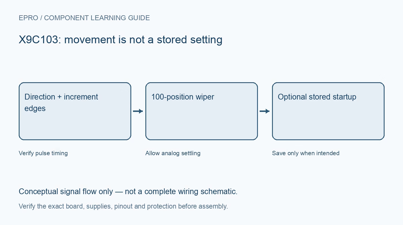
An X9C103 is a nominal ten-kilohm digital potentiometer with one hundred wiper positions and nonvolatile position storage. Its three control wires are not a conventional SPI register interface. Understand pulse timing and the distinction between moving and storing the wiper before choosing it for a signal-level adjustment.
Verify the exact device and supply
The X9C family includes several resistance values. Confirm X9C103 and the package pinout rather than relying on a generic module title. The documented supply is five volts with its specified tolerance, not a general three-point-three-volt supply option. Check host input thresholds separately from the analog terminal limits.
Understand the one-hundred-position network
Ninety-nine resistor elements provide one hundred tap points. The nominal end-to-end resistance has a substantial tolerance, and the wiper adds switch resistance. It is not an eight-bit 256-position pot or an exact ten-kilohm standard. Check the loaded divider or rheostat behavior at the intended settings.
Assess terminal voltages during sequencing
The documented terminal range includes negative and positive voltages under stated conditions, but terminal voltages must also satisfy the supply-related power-up and power-down requirements. Do not apply the headline range to an unpowered chip. Start with positive low-voltage signals and verify current limits before considering more complex arrangements.
Use edge-controlled movement
With chip select active, falling transitions on INC move the wiper according to U/D. Direction setup and pulse timing matter. A generic SPI byte is not an absolute position command. The counter stops at either endpoint rather than wrapping, but software must still know how it established a reference position.
Separate adjustment from nonvolatile storage
Raising chip select while INC is high initiates a store of the current position. Deselecting with INC low avoids that store. This distinction allows temporary adjustments without consuming a nonvolatile write for every movement. Follow the documented sequence and timing rather than assuming all deselections have the same effect.
Budget endurance and settling
Nonvolatile storage has a finite endurance and needs its specified store interval. Avoid saving in a continuously running control loop. Wiper transitions also require settling, and the make-before-break switching behavior can momentarily alter the effective resistance network. Sensitive feedback circuits need a fuller transient analysis than a static resistance check.
Newest in the store


Define a low-energy first application
Begin with a safe lightly loaded divider and measure movement, endpoint behavior and a deliberately saved power-up position. Check noise and loading before claiming precision. This component is not a power regulator, isolation barrier or safety interlock, and an experiment does not certify it as a universal mechanical-pot replacement.
Frequently asked questions
Can an SPI library write position fifty directly?
Not through a normal SPI register transaction; X9C103 uses direction and increment pulses.
Does every adjustment need to be saved?
No. The documented no-store deselection permits temporary changes without a nonvolatile write.
Availability and illustration note
No matching Epro product was returned by the catalog search on 21 October 2026 UTC. This learning guide does not assert stock, a selling price or compatibility of an unidentified substitute. The illustration is an original conceptual signal-flow diagram, not a product photograph or complete wiring schematic.
Related Epro reading
For a first bench setup, review breadboard connections and continuity checks and I2C voltage-level translation. These guides do not replace the exact module schematic.
Technical references and limitations
Source: Renesas X9C102/X9C103/X9C104/X9C503 datasheet. Electrical limits apply to the named part, not automatically to every carrier board. This is a documentation-based learning workflow, not a claim of independent hardware testing, traceable calibration or safety certification.