


INA260 Power Monitor: 7 Checks Beyond the Integrated Shunt

INA260 Power Monitor: 7 Checks Beyond the Integrated Shunt
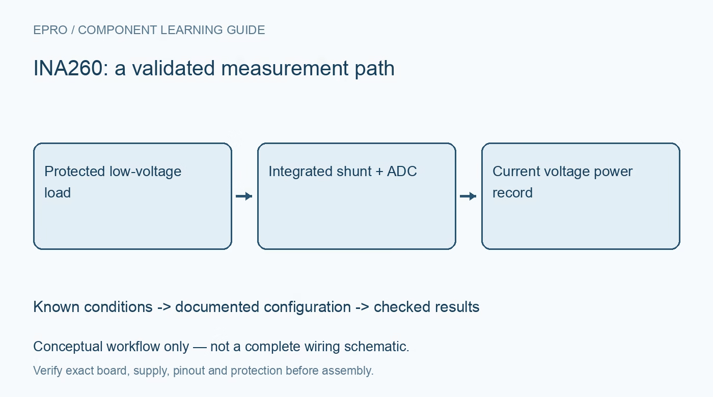
Plan INA260 measurements with current-path inspection, connector limits, conversion timing and low-voltage validation instead of assuming every board handles the IC rating. This is a documentation-based bench-planning guide, not a claim of independent hands-on testing.
1. Understand the INA260 difference
The INA260 measures current, bus voltage and power through a digital interface and integrates a precision shunt into the device. Texas Instruments specifies a 2 milliohm internal current-sense resistance. This removes one external shunt-selection step, but it does not remove current-path heating, connector limits or layout requirements. Define the expected continuous current, startup surge and acceptable voltage loss before choosing a module for a low-voltage project. Manufacturer documentation.
2. Trace the current path before wiring
Identify the designated current-input and current-output connections, logic supply and signal ground on the actual board. Current must pass through the intended shunt path, not through a microcontroller header or a parallel bypass wire. Inspect terminals, solder joints, copper width and the carrier documentation. The IC current capability is not automatically the assembled module rating. Never increase a test current merely because an online listing repeats a chip-level maximum.
3. Separate bus voltage from logic power
The manufacturer describes bus sensing from 0 V to 36 V and a separate 2.7 V to 5.5 V device supply. Those are different electrical requirements. Check pull-up levels and controller compatibility independently, and keep grounds within the documented arrangement. Bus voltage is not permission to connect mains or an unknown high-energy source. An INA260 module does not provide galvanic isolation simply because it reports measurements digitally. Manufacturer documentation.
4. Begin with a small protected load
Use a fused or appropriately current-limited low-voltage source and a modest known load. Confirm wiring with power removed, then compare current direction and voltage against an independent instrument. Choose a suitable current range on that instrument before inserting it into a circuit. Start near zero and increase gradually only within the complete assembly limits. Stop if terminals warm unexpectedly, readings jump or the supply enters an unexplained limiting state.Newest in the store


5. Respect conversion and averaging settings
Conversion time and averaging change response speed and noise. A smoothed current value may hide a short startup surge, while rapid polling may return unchanged conversion data. Follow the documented ready and alert behavior rather than assuming each register read initiates a measurement. Record the configuration with your samples. Validate the timing using a controlled load change before relying on a threshold to trigger application logic.
6. Do not confuse power with energy
The INA260 provides power information, but energy logging needs integration over elapsed time with consistent units and handling of missing samples. A simple average multiplied by an assumed interval can drift when the host stalls. Preserve timestamps and current sign, and define whether reverse flow is accumulated separately. Alerts are useful status signals, not a replacement for fuses, rated protection or a properly engineered independent safety function. Manufacturer documentation.
7. Keep a credible INA260 validation log
Record source voltage, load, current direction, module identity, conversion settings and comparison-instrument uncertainty. Repeat the low-current check after the assembly reaches normal operating temperature. The existing INA219 guide explains external-shunt considerations, but its calibration procedure should not be copied blindly to this integrated-shunt device. An INA260 design becomes trustworthy through measured current-path behavior and explicit limits, not solely through a plausible number on an I2C display.
Related reading: INA219 Current Sensor: 7 Buying and Calibration Checks. For current listings, check the Epro catalog; a matching item was not returned by the exact-part catalog search on 22 October 2026. No price, stock or included-accessory claim is made here.