


MAX30102 Sensor: 7 Steps to Trustworthy Red and Infrared Samples

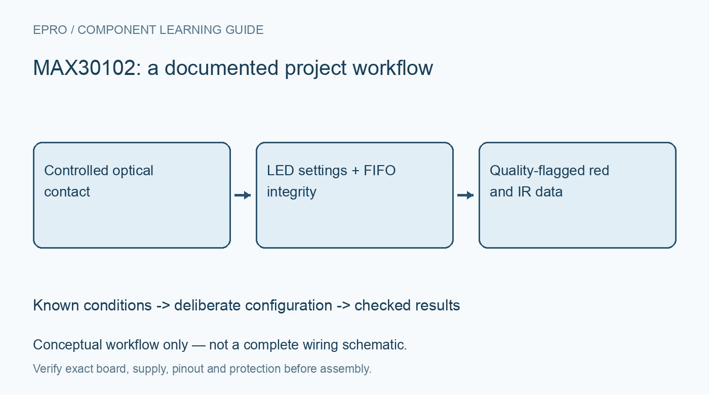
MAX30102 Sensor: 7 Steps to Trustworthy Red and Infrared Samples
Capture MAX30102 red and infrared data with safe board identification, FIFO checks and optical-quality flags before attempting pulse estimation. This is a documentation-based project guide, not an independent hands-on test report.
1. Start with optical data, not a diagnosis
MAX30102 integrates red and infrared emitters with optical sensing and digital data handling. Analog Devices describes it for pulse-oximetry and heart-rate applications, but the component alone does not make a validated medical instrument. This guide focuses on collecting interpretable raw channels. Do not use a hobby prototype to make treatment decisions, assess an emergency or replace a certified device. An attractive heart-rate number is not evidence of clinical accuracy. Manufacturer documentation.
2. Verify the carrier power architecture
The bare device uses separate sensor and LED supply arrangements. A breakout may add regulation or interface circuitry, but inspect its schematic before connecting a controller. Confirm the input supply, pull-up voltages, ground connections and actual part identity. Do not infer five-volt logic compatibility from a board power label. Keep wiring short and check decoupling because pulsed LED current can create supply disturbances that appear in the optical record. Manufacturer documentation.
3. Choose a coherent acquisition configuration
Set the operating mode, LED channels, sample rate, pulse width, ADC range and averaging together using supported combinations. Start with conservative documented settings rather than maximum LED current. A higher setting is not automatically a better measurement. Save the entire configuration so a trace can be reproduced. If averaging decimates the output, use the effective FIFO sample cadence when interpreting time rather than the unadjusted conversion-rate setting. Manufacturer documentation.
4. Read complete FIFO samples
The FIFO stores channel data according to the active acquisition mode. Read complete channel groups, preserving the documented byte order and significant bits. Keep red and infrared samples aligned rather than taking unrelated values as a pair. Monitor read and write pointers and the overflow condition. If the host is delayed, flag lost data and restart analysis as required. Quietly joining separated segments can create false periodic structure in a pulse estimator. Manufacturer documentation.
Newest in the store


5. Control contact, light and motion
Use consistent, comfortable optical contact without excessive pressure and keep the assembly electrically safe and enclosed. Observe the raw channels while the sensor is uncovered, gently covered and held still. Check for clipping, weak modulation and sudden movement artifacts before interpreting periodic changes. Ambient-light rejection is helpful but not permission to ignore enclosure design. Keep an explicit signal-quality state so a detached or moving sensor does not continue showing an old plausible value. Manufacturer documentation.
6. Keep algorithms separate from measurements
Pulse estimation requires timing, filtering, peak selection and rejection rules beyond a register read. Oxygen-saturation estimates require an appropriate validated processing and calibration path; a copied ratio equation is not sufficient evidence. Report raw samples and algorithm-derived results as different quantities. Do not label the internal temperature reading as body temperature without an appropriate validated method. Reject poor-quality windows instead of forcing every block of samples to produce a health-related number. Manufacturer documentation.
7. Record MAX30102 limitations with the trace
Store settings, effective sample interval, raw channels, overflow flags and quality decisions alongside any experimental estimates. Test recovery after removing optical contact and after a host read pause. The related spectral-sensor guide illustrates controlled optical measurement, not a medically interchangeable technique. For the matching Epro module listing, inspect the actual carrier details before purchase. This article claims neither clinical performance nor that a particular shipped board has the same power circuitry as an example. Manufacturer documentation.
Related reading: AS7341 Spectral Sensor: 7 Checks for Repeatable Color Data.
Matching catalog listing: Max30102 Heart Rate Sensor Pulse Detection Blood Oxygen Concentration Module in Pakistan. Confirm the actual carrier schematic and included items before ordering; no current price or stock promise is made here.