


AS7341 Spectral Sensor: 7 Checks for Repeatable Color Data

AS7341 Spectral Sensor: 7 Checks for Repeatable Color Data
Use AS7341 spectral measurements responsibly by checking carrier voltage, SMUX mapping, exposure, illumination and calibration before comparing color samples. This is a documentation-based bench-planning guide, not a claim of independent hands-on testing.
1. Understand the AS7341 measurement
The AS7341 provides filtered optical channels rather than a continuous high-resolution laboratory spectrum. Its manufacturer describes eight visible channels plus near-infrared, clear and flicker functions. These responses can help compare controlled light or material samples, but raw counts do not identify an unknown chemical or prove material purity. Define a modest repeatability task before purchasing hardware, such as distinguishing known samples under one fixed illumination arrangement. Manufacturer documentation.
2. Check the carrier power design
The bare sensor operates around a 1.8 V supply, with the datasheet specifying its allowed range separately from digital-pin ratings. Breakout boards may include regulation and level translation, but those additions must be verified from the actual schematic. Identify the optical opening, supply terminals, pull-ups and any illumination LED. Never infer a safe host voltage merely because another seller uses the same sensor name.
3. Configure the AS7341 SMUX correctly
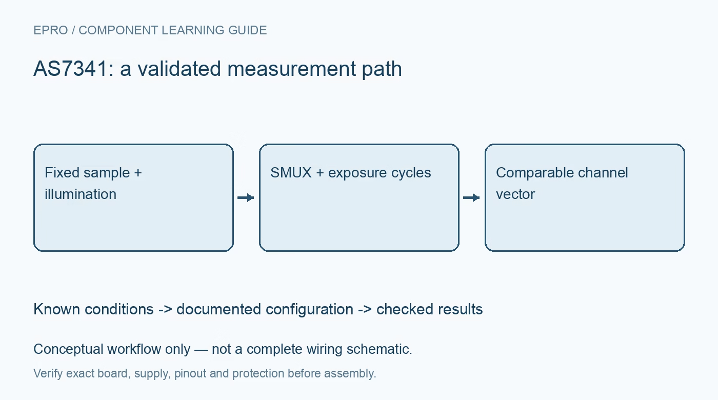
The sensor maps photodiodes through its SMUX to six available conversion channels. Measurements covering more than six channels require multiple integration cycles; eleven named functions do not mean eleven simultaneously sampled ADCs. Use the documented mapping and confirm which channel each returned value represents. Keep clear and near-infrared samples associated with their measurement cycle. A mislabeled array can create a plausible-looking but physically incorrect color plot. Manufacturer documentation.
4. Keep exposure and timing comparable
Gain and integration time affect counts. Choose settings that avoid saturation while retaining useful signal above the dark response, then store those settings with every sample. Do not compare unnormalized counts collected with different exposures. If the source or target moves between SMUX cycles, the combined channel vector may describe different conditions. Hold the sample still and allow a complete measurement sequence to finish before displaying a result.Newest in the store


5. Control the optical arrangement
Use a repeatable distance, angle, aperture and background. For reflection measurements, stabilize the illuminator and shield the sample from changing room light. Take a dark reading and a reference reading under documented conditions. Fingerprints, cover windows and mounting shadows can alter the response. A strong difference between two trials may reflect geometry rather than material. Record whether illumination came from the carrier LED or an external source.
6. Separate counts from calibrated conclusions
A channel count is not automatically lux, a standardized color coordinate or spectral irradiance. Such quantities require an appropriate model and calibration for the optical system and source. Start by reporting relative channel vectors and repeatability across known references. Flicker detection is a separate function with its own configuration and resource mapping. Do not interpret a flicker flag as proof that an electrical installation is safe. Manufacturer documentation.
7. Build a defensible AS7341 sample record
Save channel mapping, cycle order, gain, integration time, dark/reference readings and sample geometry with the raw data. Reject saturated or incomplete cycles instead of inventing missing channels. The existing TCS34725 guide provides RGBC context, but the sensors are not interchangeable measurement systems. An AS7341 project succeeds when repeated trials under the same conditions agree and any claimed classification is validated against independent known samples.
Related reading: TCS34725 Color Sensor: RGBC Modules and Buying Checks. For current listings, check the Epro catalog; a matching item was not returned by the exact-part catalog search on 22 October 2026. No price, stock or included-accessory claim is made here.