


TCS34725 Color Sensor: RGBC Modules and Buying Checks

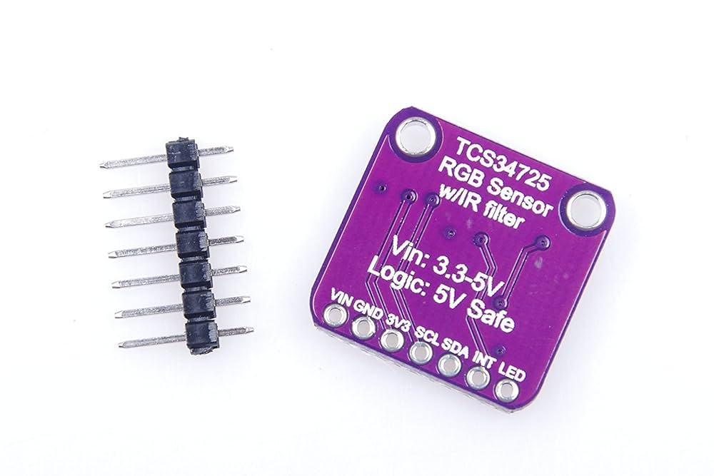
The TCS34725 measures red, green, blue and clear-channel light through an I2C interface. It can support controlled color-sensing experiments, but a module does not automatically recognize every object or produce camera-ready RGB values. Choose it by electrical compatibility, illumination, measurement range and how repeatable your target position will be.
Know what the four channels represent

The sensor contains filtered photodiodes and integrating ADCs. The clear channel is a broad light measurement, not an alpha transparency channel from a graphics file. Raw R, G and B counts depend on gain, integration and the light arriving at the detector. They cannot be compared fairly across different settings without accounting for those changes.
Inspect regulator and logic-level arrangements
The TCS34725 IC has a specified supply range of 2.7–3.6 V. Some development boards add regulation and level shifting, while others do not. Check the actual breakout schematic, supply pin naming and I2C pull-up rail. A claim that a module accepts 5 V power does not by itself establish that every signal is safe for a 3.3 V host.
Check the fixed address and bus plan
The TCS34725 uses the 7-bit address 0x29. Two identical fixed-address modules need separate supported buses or a suitable I2C multiplexer if they must be individually selected. Check other devices before assembly because some unrelated sensors share this address. An address collision can look like intermittent software failure.
Plan gain and integration time
The device offers programmable gain and integration time. Higher gain or longer integration can help weak signals, but can also saturate a channel under strong illumination. Saturation depends on integration settings and is not always only a count of 65535. Log all four raw channels and the configuration when deciding whether a measurement is within range.
Control illumination and geometry
For reflective targets, use stable illumination and a fixed target distance and angle. Glossy surfaces can produce strong reflections that differ from a matte sample of the same apparent color. Ambient sunlight can change the result even when an onboard lamp is present. A small opaque fixture can improve repeatability, but it does not turn the sensor into a laboratory spectrometer.
Set realistic color-classification goals
Start with a limited set of known samples and collect repeated readings under the intended conditions. Use a separate set of samples to check a proposed threshold rule. Normalizing channel ratios can reduce some brightness variation, but cannot correct arbitrary lighting spectra or a saturated detector. State the conditions under which a label is expected to work.Newest in the store


Relevant Epro listing
Product information and prices were checked on 19 October 2026. This is a current snapshot, not a historical price associated with the publication timestamp. Stock, accessories and checkout prices can change. Listing claims are not independent performance or authenticity certifications.
| Product | Checked price | Stock |
|---|---|---|
| TCS34725 Digital Color Detection Sensor – RGB & Light Sensing Module | PKR 970 | In stock |
Frequently asked questions
Are the raw values standard display RGB?
No. They are sensor channel counts affected by illumination, gain and integration. Additional processing and calibration are needed for a particular task.
Does the clear channel measure transparency?
Not in the graphics-file sense. It is a broad light channel used alongside the filtered color channels.
Related Epro reading
Review breadboard connections before assembling a prototype. For controller expansion, the Mega 2560 pin guide explains why pin names and electrical limits must be checked together.
Technical references and test limitations
This guide uses the documentation linked below. The procedures are for a controlled, low-voltage learning setup; no independent hands-on test of the particular seller board is claimed. Record the actual part markings, wiring and firmware version before drawing conclusions from a test.