


MAX31856 Thermocouple Interface: 7 Decisions Beyond Type K

MAX31856 Thermocouple Interface: 7 Decisions Beyond Type K
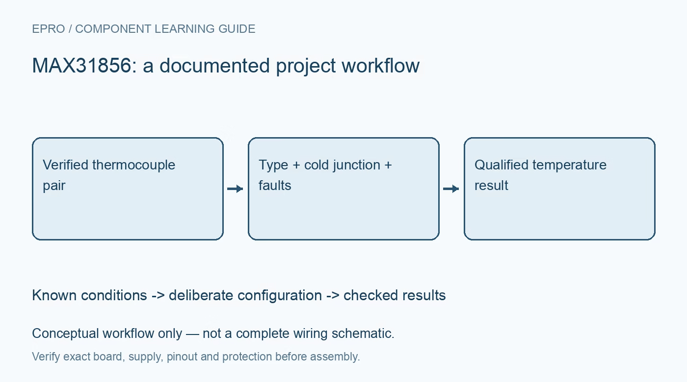
Select MAX31856 thermocouple type, noise filtering and fault policy while checking cold-junction layout and complete signed temperature readout. This is a documentation-based planning guide, not a report of independent hands-on testing.
1. Select the actual thermocouple type
MAX31856 supports several thermocouple types through configurable linearization. Analog Devices documents this as a programmable thermocouple-to-digital interface with cold-junction compensation, not a resistance-temperature detector interface. Identify the probe, connector and extension-wire type before choosing the register setting. A common connector color alone is not universal evidence because color conventions differ. The default configuration should never substitute for identifying what has actually been connected to the input. Manufacturer documentation.
2. Separate probe limits from converter limits
The converter can represent temperatures beyond the usable range of many inexpensive probes, cable insulations and connectors. Record the complete measurement assembly limits and the relevant thermocouple range. Inspect the breakout supply and logic circuitry before connecting SPI signals. Do not interpret input-protection specifications as permission to touch live conductors with a probe. This guide is for an electrically isolated, controlled measurement setup and does not establish safe direct contact with mains equipment. Manufacturer documentation.
3. Design the cold-junction thermal path
Cold-junction compensation depends on the thermal relationship between the thermocouple-to-copper transitions and the compensation sensor. Keep these transitions away from local heat sources and steep airflow gradients. A warm regulator beside a connector can matter even when the SPI data are perfect. The device has documented options for externally supplied cold-junction information, but using them requires an appropriate external measurement and thermal design rather than a fixed guessed room-temperature number. Manufacturer documentation.
4. Choose filtering before starting conversions
Select the documented line-frequency rejection setting for the environment and choose averaging according to the response requirement. Additional averaging increases conversion time. Follow the restrictions on changing settings while conversions are active. Decide whether the application uses one-shot or automatic acquisition, and wait for the correct data-ready behavior. Refreshing a screen quickly does not shorten the thermal response of the probe or the configured conversion sequence. Manufacturer documentation.
Newest in the store


5. Read the signed result coherently
Read all temperature result bytes using the documented multibyte transaction so they belong to the same update. Decode sign extension, bit alignment and scale separately for thermocouple and cold-junction values. Keep raw bytes during development and test interpretation around zero using suitable controlled conditions. The smallest output increment is resolution, not a guarantee that the probe assembly achieves that absolute accuracy. Include probe tolerance and reference uncertainty when judging differences. Manufacturer documentation.
6. Define faults as application states
Configure open-circuit detection and fault thresholds deliberately. Understand fault masks, latch behavior and clearing requirements before interpreting a fault pin. A masked notification does not make the underlying input valid. Log the fault register with the associated reading and reject invalid observations. Test recovery by disconnecting the probe only in a safe unpowered or suitably isolated setup; do not create deliberate overvoltage conditions to demonstrate protection. Manufacturer documentation.
7. Keep MAX31856 results defensible
Store thermocouple type, filter, averaging, cold-junction value, fault status and timestamp with each accepted temperature. Compare a stable safe condition with a suitable reference before attempting a broader range. Keep independent overtemperature protection where failure could cause harm. The linked MAX31855 guide introduces cold-junction concepts, but its interface and fixed-type assumptions cannot be copied blindly. A defensible MAX31856 reading comes from a compatible probe, thermal design and explicit validity policy. Manufacturer documentation.
Related reading: MAX31855 Thermocouple Module: 7 Cold-Junction Checks.
Catalog note: The exact-part search did not return a matching Epro listing during preparation. Check the current catalog; this guide makes no price, availability or included-accessory claim.