


MCP3421 ADC: 7 Trade-Offs Between Resolution and Sample Rate

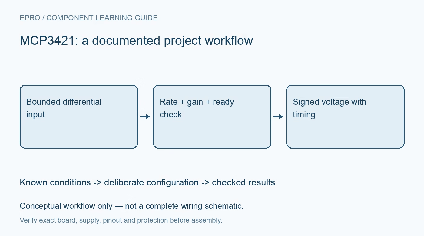
MCP3421 ADC: 7 Trade-Offs Between Resolution and Sample Rate
Choose MCP3421 resolution, gain and one-shot timing while decoding variable-length signed results and respecting differential input limits. This is a documentation-based planning guide, not a report of independent hands-on testing.
1. Understand the MCP3421 measurement role
MCP3421 is a single-channel differential delta-sigma ADC with an internal reference and programmable gain. Microchip documents selectable resolution and conversion rate, making it useful for slowly changing bounded analog signals. It is not a simultaneous multichannel recorder or a fast waveform digitizer. Write down the required signal bandwidth, expected voltage and acceptable latency before choosing a mode. The highest advertised bit count is meaningful only alongside its corresponding acquisition rate. Manufacturer documentation.
2. Keep each input electrically valid
A differential input measures the voltage difference between two pins, but both pins still have supply-relative limits. Selecting a gain or a smaller differential range does not provide input protection or electrical isolation. Check the source common-mode voltage, possible faults and loading. Use a protected low-voltage source for initial tests. Do not attach the ADC directly to mains, an unknown industrial signal or a battery arrangement outside the board and device limits. Manufacturer documentation.
3. Choose the resolution-rate pair deliberately
The documented options range from twelve-bit acquisition at 240 samples per second to eighteen-bit acquisition at 3.75 samples per second, with intermediate modes. A display that refreshes ten times per second cannot obtain ten independent eighteen-bit results each second from this converter. Select the mode for the signal and host schedule, then record it. Distinguish nominal conversion rate from observed valid-sample timing when the bus or processor introduces delays. Manufacturer documentation.
4. Apply gain without confusing accuracy
Select programmable gain to use a suitable portion of the differential range without saturation. Use the documented scale for the chosen resolution and gain when converting counts to voltage. A higher gain can help with small inputs but does not eliminate reference, offset, source or noise errors. Check source impedance and filtering against the acquisition requirements. A smooth average with many decimal places is not an independent demonstration of measurement accuracy. Manufacturer documentation.
Newest in the store


5. Decode the correct result length
Different resolution modes use different conversion-data lengths before the configuration byte. Read the format required for the selected mode and reconstruct the signed result with the documented alignment. Do not treat the configuration byte as another sample byte or use an eighteen-bit decoder for every setting. Preserve raw transfers during bring-up, including returned configuration. Confirm that the effective resolution and gain match the settings used by the voltage conversion code. Manufacturer documentation.
6. Require a fresh completed conversion
Use the documented ready indication to distinguish a completed result from an in-progress conversion. In one-shot mode, trigger acquisition intentionally and apply a bounded timeout; in continuous mode, preserve the timing relationship between reads and updates. Reading repeatedly does not create fresh samples. Track rejected transfers and stale results separately. After a configuration change, follow the documented sequencing so an old conversion is not mislabeled with the new gain or resolution. Manufacturer documentation.
7. Validate a small MCP3421 voltage record
Compare zero differential and several modest known input values while keeping both pins inside their allowed limits. Log raw data, returned configuration, ready state, gain, resolution, decoded voltage and timestamp. Record uncertainty in the source and reference meter. The related MCP3424 guide explains comparable ADC trade-offs, but it includes channel selection not present here. A useful MCP3421 project makes latency and validity visible instead of equating eighteen output bits with eighteen accurate bits. Manufacturer documentation.
Related reading: MCP3424 ADC: 7 Resolution and Differential Checks.
Catalog note: The exact-part search did not return a matching Epro listing during preparation. Check the current catalog; this guide makes no price, availability or included-accessory claim.